Intel 640 User Guide - Page 35
Operating System and Application Software, Considerations, On-Die Thermal Diode
 |
UPC - 683728178901
View all Intel 640 manuals
Add to My Manuals
Save this manual to your list of manuals |
Page 35 highlights
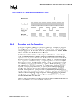
Thermal Management Logic and Thermal Monitor Feature R For information regarding THERMTRIP#, refer to the processor datasheet and to Section 4.2.8 of this Thermal Design Guidelines. 4.2.6 Operating System and Application Software Considerations The Thermal Monitor feature and its thermal control circuit work seamlessly with ACPI compliant operating systems. The Thermal Monitor feature is transparent to application software since the processor bus snooping, ACPI timer, and interrupts are active at all times. 4.2.7 On-Die Thermal Diode There are two independent thermal sensing devices in the Pentium 4 processor in the 775-land LGA package. One is the on-die thermal diode and the other is in the temperature sensor used for the Thermal Monitor and for THERMTRIP#. The Thermal Monitor's temperature sensor and the on-die thermal diode are independent and physically isolated devices. Circuit constraints and performance requirements prevent the Thermal Monitor's temperature sensor and the on-die thermal diode from being located at the same place on the silicon. The temperature distribution across the die may result in significant temperature differences between the on-die thermal diode and the Thermal Monitor's temperature sensor. This temperature variability across the die is highly dependent on the application being run. As a result, it is not possible to predict the activation of the thermal control circuit by monitoring the on-die thermal diode. System integrators should note that there is no defined correlation between the on-die thermal diode and the processor case temperature. The temperature distribution across the die is affected by the power being dissipated, type of activity the processor is performing (e.g., integer or floating point intensive), and the leakage current. The dynamic and independent nature of these effects makes it difficult to provide a meaningful correlation for the processor population. System integrators that plan on using the thermal diode for system or component level fan control to optimize acoustics need to refer to Acoustic Fan Control, Section 6.1. 4.2.7.1 Reading the On-Die Thermal Diode Interface The on-die thermal diode is accessible from a pair of pins on the processor. The fan speed controller remote thermal sense signals should be connected to these pins per the vendor's recommended layout guidelines. Table 1. Thermal Diode Interface Pin Name THERMDA THERMDC Pin Number AL1 AK1 Pin Description Diode anode Diode anode Thermal/Mechanical Design Guide 35
-
 1
1 -
2
-
3
-
4
-
5
-
6
-
7
-
8
-
9
-
10
-
11
-
12
-
13
-
14
-
15
-
16
-
17
-
18
-
19
-
20
-
21
-
22
-
23
-
24
-
25
-
26
-
27
-
28
-
29
-
 30
30 -
 31
31 -
 32
32 -
 33
33 -
 34
34 -
 35
35 -
 36
36 -
 37
37 -
 38
38 -
 39
39 -
 40
40 -
41
-
42
-
43
-
44
-
45
-
46
-
47
-
48
-
49
-
50
-
51
-
52
-
53
-
54
-
55
-
56
-
57
-
58
-
59
-
60
-
61
-
62
-
63
-
64
-
65
-
66
-
67
-
68
-
69
-
70
-
71
-
72
-
73
-
74
-
75
-
76
-
77
-
78
-
79
-
80
-
81
-
82
-
83
-
84
-
85
-
86
-
87
-
88
-
89
-
90
-
91
-
92
-
93
-
94
-
95
-
96
-
97
-
98
-
99
-
100
-
101
-
102
-
103
-
104
-
105
 |
 |