Intel 640 User Guide - Page 65
A.2.5, Additional Considerations
 |
UPC - 683728178901
View all Intel 640 manuals
Add to My Manuals
Save this manual to your list of manuals |
Page 65 highlights
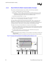
LGA775 Socket Heatsink Loading R A.2.5 A.2.5.1 Additional Considerations Intel recommends designing to {d_BOL - d_ref = 0.15mm} at BOL when EOL conditions are not known or difficult to assess. The following information is given for illustration purposes only. It is based on the reference keep-out, assuming there is no fixture that changes board stiffness: d_ref is expected to be 0.18 mm on average, and be as high as 0.22 mm. As a result, the board should be able to deflect 0.37 mm minimum at BOL. Additional deflection, as much as 0.09 mm may be necessary to account for additional creep effects impacting the board/clip/fastener assembly. As a result, designs could see as much as 0.50 mm total downward board deflection under the socket. In addition to board deflection, other elements need to be considered to define the space needed for the downward board total displacement under load, like the potential interference of throughhole mount component pin tails of the board with a mechanical fixture on the back of the board. NOTES: 1. The heatsink preload must remain below the maximum load limit of the package at all times (Refer to processor datasheet). 2. Board deflection should not exceed motherboard manufacturer specifications. Motherboard Stiffening Considerations To protect LGA775 socket solder joint, designers need to drive their mechanical design to: • Allow downward board deflection to put the socket balls in a desirable force state to protect against fatigue failure of socket solder joint (refer to Sections A.2.1, A.2.2, and A.2.3). • Prevent board upward bending during mechanical shock event. • Define load paths that keep the dynamic load applied to the package within specifications published in the processor datasheet. Limiting board deflection may be appropriate in some situations like: • Board bending during shock. • Board creep with high heatsink preload. However, the load required to meet the board deflection recommendation (refer to Section A.2.3) with a very stiff board may lead to heatsink preloads exceeding package maximum load specification. For example, such a situation may occur when using a backing plate that is flush with the board in the socket area, and prevents the board from bending underneath the socket. Thermal/Mechanical Design Guide 65
-
 1
1 -
2
-
3
-
4
-
5
-
6
-
7
-
8
-
9
-
10
-
11
-
12
-
13
-
14
-
15
-
16
-
17
-
18
-
19
-
20
-
21
-
22
-
23
-
24
-
25
-
26
-
27
-
28
-
29
-
30
-
31
-
32
-
33
-
34
-
35
-
36
-
37
-
38
-
39
-
40
-
41
-
42
-
43
-
44
-
45
-
46
-
47
-
48
-
49
-
50
-
51
-
52
-
53
-
54
-
55
-
56
-
57
-
58
-
59
-
 60
60 -
 61
61 -
 62
62 -
 63
63 -
 64
64 -
 65
65 -
 66
66 -
 67
67 -
 68
68 -
 69
69 -
 70
70 -
71
-
72
-
73
-
74
-
75
-
76
-
77
-
78
-
79
-
80
-
81
-
82
-
83
-
84
-
85
-
86
-
87
-
88
-
89
-
90
-
91
-
92
-
93
-
94
-
95
-
96
-
97
-
98
-
99
-
100
-
101
-
102
-
103
-
104
-
105
 |
 |