Intel 640 User Guide - Page 67
Appendix B Heatsink Clip Load, Metrology
 |
UPC - 683728178901
View all Intel 640 manuals
Add to My Manuals
Save this manual to your list of manuals |
Page 67 highlights
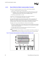
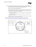
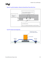
Heatsink Clip Load Metrology R Appendix B Heatsink Clip Load Metrology B.1 Overview This section describes a procedure for measuring the load applied by the heatsink/clip/fastener assembly on a processor package. This procedure is recommended to verify the preload is within the design target range for a design, and in different situations. For example: • Heatsink preload for the LGA775 socket. • Quantify preload degradation under bake conditions. Note: This document reflects the current metrology used by Intel. Intel is continuously exploring new ways to improve metrology. Updates will be provided later as this document is revised as appropriate. B.2 Test Preparation B.2.1 Heatsink Preparation Three load cells are assembled into the base of the heatsink under test, in the area interfacing with the processor Integrated Heat Spreader (IHS), using load cells equivalent to those listed in Section B.2.2. To install the load cells, machine a pocket in the heatsink base, as shown in Figure 24 and Figure 25. The load cells should be distributed evenly, as close as possible to the pocket walls. Apply wax around the circumference of each load cell and the surface of the pocket around each cell to maintain the load cells in place during the heatsink installation on the processor and motherboard (Refer to Figure 25). The depth of the pocket depends on the height of the load cell used for the test. It is necessary that the load cells protrude out of the heatsink base. However, this protrusion should be kept minimal, as it will create additional load by artificially raising the heatsink base. The measurement offset depends on the whole assembly stiffness (i.e. motherboard, clip, fastener, etc.). For example, the Intel RCBFH-3 Reference Heatsink Design clip and fasteners assembly has a stiffness of around 380 N/mm [2180 lb/in]. In that case, a protrusion of 0.038 mm [0.0015"] will create an extra load of 15 N [3.3 lb]. Figure 26 shows an example using the Intel RCBFH-3 Reference Heatsink designed for the Pentium 4 processor in the 775-land LGA package. Thermal/Mechanical Design Guide 67
-
 1
1 -
2
-
3
-
4
-
5
-
6
-
7
-
8
-
9
-
10
-
11
-
12
-
13
-
14
-
15
-
16
-
17
-
18
-
19
-
20
-
21
-
22
-
23
-
24
-
25
-
26
-
27
-
28
-
29
-
30
-
31
-
32
-
33
-
34
-
35
-
36
-
37
-
38
-
39
-
40
-
41
-
42
-
43
-
44
-
45
-
46
-
47
-
48
-
49
-
50
-
51
-
52
-
53
-
54
-
55
-
56
-
57
-
58
-
59
-
60
-
61
-
 62
62 -
 63
63 -
 64
64 -
 65
65 -
 66
66 -
 67
67 -
 68
68 -
 69
69 -
 70
70 -
 71
71 -
 72
72 -
73
-
74
-
75
-
76
-
77
-
78
-
79
-
80
-
81
-
82
-
83
-
84
-
85
-
86
-
87
-
88
-
89
-
90
-
91
-
92
-
93
-
94
-
95
-
96
-
97
-
98
-
99
-
100
-
101
-
102
-
103
-
104
-
105
 |
 |