Intel 640 User Guide - Page 27
Processor Thermal Solution Performance, Assessment, Local Ambient Temperature Measurement,
 |
UPC - 683728178901
View all Intel 640 manuals
Add to My Manuals
Save this manual to your list of manuals |
Page 27 highlights
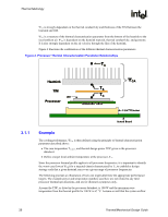
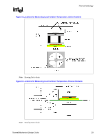
Thermal Metrology R has been designed such that the local ambient temperature is 38 °C. Then the following could be calculated using Equation 1 from above: ΨCA = (TC - TA) / TDP = (67 - 38) / 100 = 0.29 °C/W To determine the required heatsink performance, a heatsink solution provider would need to determine ΨCS performance for the selected TIM and mechanical load configuration. If the heatsink solution were designed to work with a TIM material performing at ΨCS ≤ 0.10 °C/W, solving for Equation 2 from above, the performance of the heatsink would be: ΨSA = ΨCA − ΨCS = 0.29 − 0.10 = 0.19 °C/W 3.2 3.3 Processor Thermal Solution Performance Assessment Thermal performance of a heatsink should be assessed using a thermal test vehicle (TTV) provided by Intel. The TTV is a stable heat source from which the user can take accurate power measurements, whereas actual processors can introduce additional factors that can impact test results. In particular, the power level from actual processors varies significantly due to variances in the manufacturing process. The TTV provides consistent power and power density for thermal solution characterization and results can be easily translated to real processor performance. Once the thermal solution is designed and validated, it is strongly recommended to verify functionality of the thermal solution on real processors and on fully integrated systems. Contact your Intel field sales representative for further information on TTV or regarding accurate measurement of the power dissipated by an actual processor. Local Ambient Temperature Measurement Guidelines The local ambient temperature TA is the temperature of the ambient air surrounding the processor. For a passive heatsink, TA is defined as the heatsink approaches air temperature; for an actively cooled heatsink, it is the temperature of inlet air to the active cooling fan. It is worthwhile to determine the local ambient temperature in the chassis around the processor to understand the effect it may have on the case temperature. TA is best measured by averaging temperature measurements at multiple locations in the heatsink inlet airflow. This method helps reduce error and eliminate minor spatial variations in temperature. The following guidelines are meant to enable accurate determination of the localized air temperature around the processor during system thermal testing. For active heatsinks, it is important to avoid taking measurement in the dead flow zone that usually develops above the fan hub and hub spokes. Measurements should be taken at four different locations uniformly placed at the center of the annulus formed by the fan hub and the fan housing to evaluate the uniformity of the air temperature at the fan inlet. The thermocouples Thermal/Mechanical Design Guide 27
-
 1
1 -
2
-
3
-
4
-
5
-
6
-
7
-
8
-
9
-
10
-
11
-
12
-
13
-
14
-
15
-
16
-
17
-
18
-
19
-
20
-
21
-
 22
22 -
 23
23 -
 24
24 -
 25
25 -
 26
26 -
 27
27 -
 28
28 -
 29
29 -
 30
30 -
 31
31 -
 32
32 -
33
-
34
-
35
-
36
-
37
-
38
-
39
-
40
-
41
-
42
-
43
-
44
-
45
-
46
-
47
-
48
-
49
-
50
-
51
-
52
-
53
-
54
-
55
-
56
-
57
-
58
-
59
-
60
-
61
-
62
-
63
-
64
-
65
-
66
-
67
-
68
-
69
-
70
-
71
-
72
-
73
-
74
-
75
-
76
-
77
-
78
-
79
-
80
-
81
-
82
-
83
-
84
-
85
-
86
-
87
-
88
-
89
-
90
-
91
-
92
-
93
-
94
-
95
-
96
-
97
-
98
-
99
-
100
-
101
-
102
-
103
-
104
-
105
 |
 |