Intel 640 User Guide - Page 64
A.2.4, Board Deflection Metric Implementation Example
 |
UPC - 683728178901
View all Intel 640 manuals
Add to My Manuals
Save this manual to your list of manuals |
Page 64 highlights
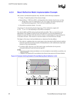
LGA775 Socket Heatsink Loading R A.2.4 Board Deflection Metric Implementation Example This section is for illustration purposes only, and relies on the following assumptions: • 72 mm x 72 mm hole pattern of the reference design • Board stiffness = 900 lb/in at BOL, with degradation that simulates board creep over time ⎯ Though these values are representative, they may change with selected material and board manufacturing process. Check with your motherboard vendor. • Clip stiffness assumed constant - No creep. Using Figure 23, the heatsink preload at beginning of life is defined to comply with d_EOL - d_ref = 0.15 mm depending on clip stiffness assumption. Note that the BOL and EOL preload and board deflection differ. This is a result of the creep phenomenon. The example accounts for the creep expected to occur in the motherboard. It assumes no creep will occur in the clip. However, there is a small amount of creep accounted for in the plastic fasteners. This situation is somewhat similar to the Intel Reference Design. The impact of the creep to the board deflection is a function of the clip stiffness: • The relatively compliant clips store strain energy in the clip under the BOL preload condition and tend to generate increasing amounts of board deflection as the motherboard creeps under exposure to time and temperature. • In contrast, stiffer clips store very little strain energy, and therefore do not generate substantial additional board deflection through life. NOTES: 1. Board and clip creep modify board deflection over time and depend on board stiffness, clip stiffness, and selected materials. 2. Designers must define the BOL board deflection that will lead to the correct end of life board deflection. Figure 23. Example: Defining Heatsink Preload Meeting Board Deflection Limit 64 Thermal/Mechanical Design Guide
-
 1
1 -
2
-
3
-
4
-
5
-
6
-
7
-
8
-
9
-
10
-
11
-
12
-
13
-
14
-
15
-
16
-
17
-
18
-
19
-
20
-
21
-
22
-
23
-
24
-
25
-
26
-
27
-
28
-
29
-
30
-
31
-
32
-
33
-
34
-
35
-
36
-
37
-
38
-
39
-
40
-
41
-
42
-
43
-
44
-
45
-
46
-
47
-
48
-
49
-
50
-
51
-
52
-
53
-
54
-
55
-
56
-
57
-
58
-
 59
59 -
 60
60 -
 61
61 -
 62
62 -
 63
63 -
 64
64 -
 65
65 -
 66
66 -
 67
67 -
 68
68 -
 69
69 -
70
-
71
-
72
-
73
-
74
-
75
-
76
-
77
-
78
-
79
-
80
-
81
-
82
-
83
-
84
-
85
-
86
-
87
-
88
-
89
-
90
-
91
-
92
-
93
-
94
-
95
-
96
-
97
-
98
-
99
-
100
-
101
-
102
-
103
-
104
-
105
 |
 |