Intel 640 User Guide - Page 68
Remarks: Alternate Heatsink Sample Preparation
 |
UPC - 683728178901
View all Intel 640 manuals
Add to My Manuals
Save this manual to your list of manuals |
Page 68 highlights
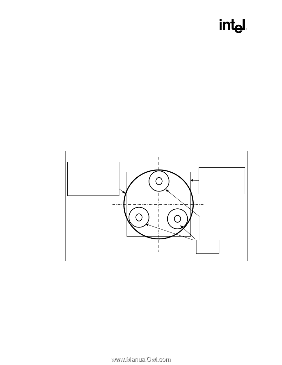
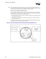
Heatsink Clip Load Metrology R Note: When optimizing the heatsink pocket depth, the variation of the load cell height should also be taken into account to make sure that all load cells protrude equally from the heatsink base. It may be useful to screen the load cells prior to installation to minimize variation. Remarks: Alternate Heatsink Sample Preparation As just mentioned, making sure that the load cells have minimum protrusion out of the heatsink base is paramount to meaningful results. An alternate method to make sure that the test setup will measure loads representative of the non-modified design is: • Machine the pocket in the heat sink base to a depth such that the tips of the load cells are just flush with the heat sink base. • Then machine back the heatsink base by around 0.25 mm [0.01"], so that the load cell tips protrude beyond the base. Proceeding this way, the original stack height of the heatsink assembly should be preserved. This should not affect the stiffness of the heatsink significantly. Figure 24. Load Cell Installation in Machined Heatsink Base Pocket (Bottom View) Heatsink Base Pocket Diameter ~ 29 mm [~1.15"] Package IHS Outline (Top Surface) Load Cells 68 Thermal/Mechanical Design Guide
-
 1
1 -
2
-
3
-
4
-
5
-
6
-
7
-
8
-
9
-
10
-
11
-
12
-
13
-
14
-
15
-
16
-
17
-
18
-
19
-
20
-
21
-
22
-
23
-
24
-
25
-
26
-
27
-
28
-
29
-
30
-
31
-
32
-
33
-
34
-
35
-
36
-
37
-
38
-
39
-
40
-
41
-
42
-
43
-
44
-
45
-
46
-
47
-
48
-
49
-
50
-
51
-
52
-
53
-
54
-
55
-
56
-
57
-
58
-
59
-
60
-
61
-
62
-
 63
63 -
 64
64 -
 65
65 -
 66
66 -
 67
67 -
 68
68 -
 69
69 -
 70
70 -
 71
71 -
 72
72 -
 73
73 -
74
-
75
-
76
-
77
-
78
-
79
-
80
-
81
-
82
-
83
-
84
-
85
-
86
-
87
-
88
-
89
-
90
-
91
-
92
-
93
-
94
-
95
-
96
-
97
-
98
-
99
-
100
-
101
-
102
-
103
-
104
-
105
 |
 |