Intel 640 User Guide - Page 33
Operation and Configuration - driver
 |
UPC - 683728178901
View all Intel 640 manuals
Add to My Manuals
Save this manual to your list of manuals |
Page 33 highlights
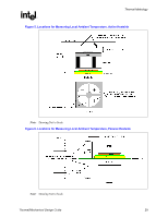
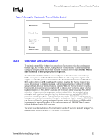
Thermal Management Logic and Thermal Monitor Feature R Figure 7. Concept for Clocks under Thermal Monitor Control PROCHOT# Normal clock Internal clock Duty cycle control Resultant internal clock 4.2.3 Operation and Configuration To maintain compatibility with previous generations of processors, which have no integrated thermal logic, the Thermal Control Circuit portion of Thermal Monitor is disabled by default. During the boot process, the BIOS must enable the Thermal Control Circuit. Thermal Monitor must be enabled to ensure proper processor operation. The Thermal Control Circuit feature can be configured and monitored in a number of ways. OEMs are required to enable the Thermal Control Circuit while using various registers and outputs to monitor the processor thermal status. The Thermal Control Circuit is enabled by the BIOS setting a bit in an MSR (model specific register). Enabling the Thermal Control Circuit allows the processor to attempt to maintain a safe operating temperature without the need for special software drivers or interrupt handling routines. When the Thermal Control Circuit has been enabled, processor power consumption will be reduced after the thermal sensor detects a high temperature (i.e., PROCHOT# assertion). The Thermal Control Circuit and PROCHOT# transitions to inactive once the temperature has been reduced below the thermal trip point, although a small time-based hysteresis has been included to prevent multiple PROCHOT# transitions around the trip point. External hardware can monitor PROCHOT# and generate an interrupt whenever there is a transition from active-to-inactive or inactive-to-active. PROCHOT# can also be configured to generate an internal interrupt which would initiate an OEM supplied interrupt service routine. Regardless of the configuration selected, PROCHOT# will always indicate the thermal status of the processor. The power reduction mechanism of thermal monitor can also be activated manually using an "ondemand" mode. Refer to Section 4.2.4 for details on this feature. Thermal/Mechanical Design Guide 33
-
 1
1 -
2
-
3
-
4
-
5
-
6
-
7
-
8
-
9
-
10
-
11
-
12
-
13
-
14
-
15
-
16
-
17
-
18
-
19
-
20
-
21
-
22
-
23
-
24
-
25
-
26
-
27
-
 28
28 -
 29
29 -
 30
30 -
 31
31 -
 32
32 -
 33
33 -
 34
34 -
 35
35 -
 36
36 -
 37
37 -
 38
38 -
39
-
40
-
41
-
42
-
43
-
44
-
45
-
46
-
47
-
48
-
49
-
50
-
51
-
52
-
53
-
54
-
55
-
56
-
57
-
58
-
59
-
60
-
61
-
62
-
63
-
64
-
65
-
66
-
67
-
68
-
69
-
70
-
71
-
72
-
73
-
74
-
75
-
76
-
77
-
78
-
79
-
80
-
81
-
82
-
83
-
84
-
85
-
86
-
87
-
88
-
89
-
90
-
91
-
92
-
93
-
94
-
95
-
96
-
97
-
98
-
99
-
100
-
101
-
102
-
103
-
104
-
105
 |
 |