Intel 640 User Guide - Page 20
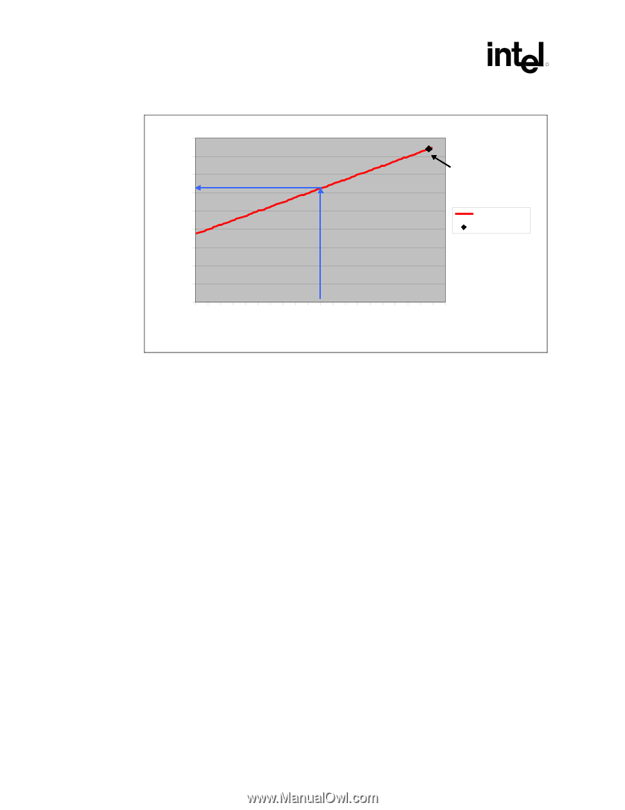
Example Thermal Profile
 |
UPC - 683728178901
View all Intel 640 manuals
Add to My Manuals
Save this manual to your list of manuals |
Page 20 highlights
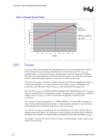
Processor Thermal/Mechanical Information R Figure 3. Example Thermal Profile Case Temperature (C) 75 70 Heatsink 65 Design Point 60 55 Thermal Profile 50 TDP 45 40 35 30 30 40 50 60 70 80 90 100 110 Watts 2.2.3 TCONTROL TCONTROL defines the maximum operating temperature for the on-die thermal diode when the thermal solution fan speed is being controlled by the on-die thermal diode. The TCONTROL parameter defines a very specific processor operating region where fan speed can be reduced. This allows the system integrator a method to reduce the acoustic noise of the processor cooling solution, while maintaining compliance to the processor thermal specification. The value of TCONTROL is driven by a number of factors. One of the most significant of these is the processor idle power. As a result, a processor with a high TCONTROL will dissipate more power than a part with lower value of TCONTROL when running the same application. The value of TCONTROL is calculated such that regardless of the individual processor's TCONTROL value, the thermal solution should perform similarly. The higher power of some parts is offset by a higher value of TCONTROL in such a way that they should behave virtually the same acoustically. This is achieved in part by using the Ψ vs. RPM and RPM vs. Acoustics (dBA) performance CA curves from the Intel enabled thermal solution. A thermal solution designed to meet the thermal profile should perform virtually the same for any value of TCONTROL. The value for TCONTROL is calculated by the system BIOS based on values read from a factory configured processor register. The result can be used to program a fan speed control component. See the processor datasheet for further details on reading the register and calculating TCONTROL. See Chapter 6, Acoustic Fan Speed Control, for details on implementing a design using TCONTROL and the Thermal Profile. 20 Thermal/Mechanical Design Guide
-
 1
1 -
2
-
3
-
4
-
5
-
6
-
7
-
8
-
9
-
10
-
11
-
12
-
13
-
14
-
 15
15 -
 16
16 -
 17
17 -
 18
18 -
 19
19 -
 20
20 -
 21
21 -
 22
22 -
 23
23 -
 24
24 -
 25
25 -
26
-
27
-
28
-
29
-
30
-
31
-
32
-
33
-
34
-
35
-
36
-
37
-
38
-
39
-
40
-
41
-
42
-
43
-
44
-
45
-
46
-
47
-
48
-
49
-
50
-
51
-
52
-
53
-
54
-
55
-
56
-
57
-
58
-
59
-
60
-
61
-
62
-
63
-
64
-
65
-
66
-
67
-
68
-
69
-
70
-
71
-
72
-
73
-
74
-
75
-
76
-
77
-
78
-
79
-
80
-
81
-
82
-
83
-
84
-
85
-
86
-
87
-
88
-
89
-
90
-
91
-
92
-
93
-
94
-
95
-
96
-
97
-
98
-
99
-
100
-
101
-
102
-
103
-
104
-
105
 |
 |