Intel 640 User Guide - Page 91
Appendix F Balanced Technology, Extended, BTX System, Thermal Considerations
 |
UPC - 683728178901
View all Intel 640 manuals
Add to My Manuals
Save this manual to your list of manuals |
Page 91 highlights
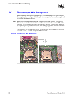
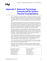
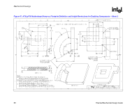
Balanced Technology Extended (BTX) System Thermal Considerations R Appendix F Balanced Technology Extended (BTX) System Thermal Considerations There are anticipated system operating conditions in which the processor power may be low but other system component powers may be high. If the only Fan Speed Control (FSC) circuit input for the Thermal Module Assembly (TMA) fan is from the processor diode, then the fan speed and system airflow is likely to be too low in this operating state. Therefore, it is recommended that a second FSC circuit input be acquired from an ambient temperature monitor location within the system. The location of the System Monitor thermal sensor is best determined through extensive systemlevel numerical thermal modeling or prototype thermal testing. In either case, the temperature of critical components or the air temperature near critical components should be assessed for a range of system external temperatures, component powers, and fan speed operating conditions. The temperature at the selected location for the System Monitor Point should be well correlated to the temperatures at or near critical components. For instance, it may be useful to monitor the temperature near the PSU airflow inlet, near the graphics add-in card, or near memory. The final system integrator is typically responsible for ensuring compliance with the component temperature specifications at all operating conditions and, therefore, should be responsible for specifying the System Monitor thermal sensor location. However, it is not always possible for a board supplier - especially a channel board supplier - to know the system into which a board will be installed. It is, therefore, important for BTX board suppliers to select a System Monitor thermal sensor location that will function properly in most systems. A BTX system should be designed such that the TMA exhaust is the primary airflow stream that cools the rest of the system. The airflow passes through the chipset heatsink and its temperature will rise as the memory controller chipset power increases. Since chipset power will increase when other subsystems (e.g., memory, graphics) are active, a System Monitor thermal sensor located in the exhaust airflow from the chipset heatsink is a reasonable location. It is likely that a thermal sensor that is not mounted above the board and in the chipset exhaust airflow will reflect board temperature and not ambient temperature. It is therefore recommended that the Thermal sensor be elevated above the board. The thermal sensor location and elevation are reflected in the Flotherm thermal model airflow illustrations (see Figure 43 and Figure 44).The Intel® Boxed Boards in BTX form factor have implemented a System Monitor thermal sensor. The following thermal sensor or its equivalent can be used for this function: Part Number: C83274-002 BizLink USA Technology, Inc. 44911 Industrial Drive Fremont, CA 94538 USA (510)252-0786 phone (510)252-1178 fax [email protected] Part Number: 68801-0170 Molex Incorporated 2222 Wellington Ct. Lisle, IL 60532 1-800-78MOLEX phone 1-630-969-1352 fax [email protected] Thermal/Mechanical Design Guide 91
-
 1
1 -
2
-
3
-
4
-
5
-
6
-
7
-
8
-
9
-
10
-
11
-
12
-
13
-
14
-
15
-
16
-
17
-
18
-
19
-
20
-
21
-
22
-
23
-
24
-
25
-
26
-
27
-
28
-
29
-
30
-
31
-
32
-
33
-
34
-
35
-
36
-
37
-
38
-
39
-
40
-
41
-
42
-
43
-
44
-
45
-
46
-
47
-
48
-
49
-
50
-
51
-
52
-
53
-
54
-
55
-
56
-
57
-
58
-
59
-
60
-
61
-
62
-
63
-
64
-
65
-
66
-
67
-
68
-
69
-
70
-
71
-
72
-
73
-
74
-
75
-
76
-
77
-
78
-
79
-
80
-
81
-
82
-
83
-
84
-
85
-
 86
86 -
 87
87 -
 88
88 -
 89
89 -
 90
90 -
 91
91 -
 92
92 -
 93
93 -
 94
94 -
 95
95 -
 96
96 -
97
-
98
-
99
-
100
-
101
-
102
-
103
-
104
-
105
 |
 |