Intel 640 User Guide - Page 39
Intel, Thermal/Mechanical, Reference Design Information
 |
UPC - 683728178901
View all Intel 640 manuals
Add to My Manuals
Save this manual to your list of manuals |
Page 39 highlights
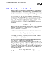
Intel® Thermal/Mechanical Reference Design Information R 5 Intel® Thermal/Mechanical Reference Design Information 5.1 Intel Validation Criteria for the Reference Design 5.1.1 Heatsink Performance Target Table 2 provides the heatsink performance target for the Pentium 4 processor in the 775-land LGA package. The thermal profiles for the Pentium 4 processor 5xx sequence and Pentium 4 processor 6xx sequence and Pentium 4 processor Extreme Edition are derived so that a single thermal solution will satisfy these processors. The table also includes a TA assumption of 38 °C for the Intel reference thermal solution at the processor fan heatsink inlet discussed Section 3.3. An external ambient temperature to the chassis of 35 °C is assumed, resulting in a temperature rise, TR, of 3 °C. Meeting TA and ΨCA targets can maximize processor performance (refer to Sections 2.2, 2.4, and Chapter 4). By minimizing TR, in the performance chassis, this helps lead to improved acoustics. Refer to the datasheet for detailed processor thermal specifications. Table 2. ATX Reference Heatsink Performance Target Processor Number Intel® Pentium® 4 Processor 670/672, 660/662, 650, 640, and 630 Intel® Pentium® 4 Processors 570/571, 560/561, 550/551, 540/541, 530/531, and 520/521 Thermal Performance, Ψca (Mean + 3σ) 0.28 °C/W Comments RCBFH-3 T Assumption A TA = 38 °C 0.29 °C/W RCBFH-3 TA = 38 °C NOTES: 1. The target performance in Table 2 is the Thermal Profile for processors with PRB=1. 2. Solutions to support processors with PRB=0 may be derived from designs supporting the thermal profile for processors with PRB=1. 3. Refer to Section 5.6 for complete description of the Intel ATX reference solution RCBFH-3. Thermal/Mechanical Design Guide 39
-
 1
1 -
2
-
3
-
4
-
5
-
6
-
7
-
8
-
9
-
10
-
11
-
12
-
13
-
14
-
15
-
16
-
17
-
18
-
19
-
20
-
21
-
22
-
23
-
24
-
25
-
26
-
27
-
28
-
29
-
30
-
31
-
32
-
33
-
 34
34 -
 35
35 -
 36
36 -
 37
37 -
 38
38 -
 39
39 -
 40
40 -
 41
41 -
 42
42 -
 43
43 -
 44
44 -
45
-
46
-
47
-
48
-
49
-
50
-
51
-
52
-
53
-
54
-
55
-
56
-
57
-
58
-
59
-
60
-
61
-
62
-
63
-
64
-
65
-
66
-
67
-
68
-
69
-
70
-
71
-
72
-
73
-
74
-
75
-
76
-
77
-
78
-
79
-
80
-
81
-
82
-
83
-
84
-
85
-
86
-
87
-
88
-
89
-
90
-
91
-
92
-
93
-
94
-
95
-
96
-
97
-
98
-
99
-
100
-
101
-
102
-
103
-
104
-
105
 |
 |