Intel 640 User Guide - Page 71
B.3.1, Time-Zero, Room Temperature Preload Measurement, B.3.2, Preload Degradation under Bake
 |
UPC - 683728178901
View all Intel 640 manuals
Add to My Manuals
Save this manual to your list of manuals |
Page 71 highlights
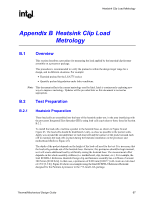
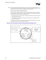
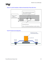
Heatsink Clip Load Metrology R B.3.1 B.3.2 Time-Zero, Room Temperature Preload Measurement 1. Pre-assemble mechanical components on the board as needed prior to mounting the motherboard on an appropriate support fixture that replicates the board attach to a target chassis. • For example: standard ATX board should sit on ATX compliant stand-offs. If the attach mechanism includes fixtures on the back side of the board, those must be included, as the goal of the test is to measure the load provided by the actual heatsink mechanism. 2. Install the test vehicle in the socket 3. Assemble the heatsink reworked with the load cells to motherboard as shown for the Intel RCBFH-3 reference heatsink example in Figure 26, and actuate attach mechanism. 4. Collect continuous load cell data at 1 Hz for the duration of the test. A minimum time to allow the load cell to settle is generally specified by the load vendors (often in the order of 3 minutes). The time zero reading should be taken at the end of this settling time. 5. Record the preload measurement (total from all three load cells) at the target time and average the values over 10 seconds around this target time as well, i.e. in the interval , for example over [target time - 5 seconds ; target time + 5 seconds]. Preload Degradation under Bake Conditions This section describes an example of testing for potential clip load degradation under bake conditions. 1. Preheat thermal chamber to target temperature (45 ºC or 85 ºC for example) 2. Repeat time-zero, room temperature preload measurement 3. Place unit into preheated thermal chamber for specified time 4. Record continuous load cell data as follows: • Sample rate = 0.1 Hz for first 3 hrs • Sample rate = 0.01 Hz for the remainder of the bake test 5. Remove assembly from thermal chamber and set into room temperature conditions 6. Record continuous load cell data for next 30 minutes at sample rate of 1 Hz. § Thermal/Mechanical Design Guide 71
-
 1
1 -
2
-
3
-
4
-
5
-
6
-
7
-
8
-
9
-
10
-
11
-
12
-
13
-
14
-
15
-
16
-
17
-
18
-
19
-
20
-
21
-
22
-
23
-
24
-
25
-
26
-
27
-
28
-
29
-
30
-
31
-
32
-
33
-
34
-
35
-
36
-
37
-
38
-
39
-
40
-
41
-
42
-
43
-
44
-
45
-
46
-
47
-
48
-
49
-
50
-
51
-
52
-
53
-
54
-
55
-
56
-
57
-
58
-
59
-
60
-
61
-
62
-
63
-
64
-
65
-
 66
66 -
 67
67 -
 68
68 -
 69
69 -
 70
70 -
 71
71 -
 72
72 -
 73
73 -
 74
74 -
 75
75 -
 76
76 -
77
-
78
-
79
-
80
-
81
-
82
-
83
-
84
-
85
-
86
-
87
-
88
-
89
-
90
-
91
-
92
-
93
-
94
-
95
-
96
-
97
-
98
-
99
-
100
-
101
-
102
-
103
-
104
-
105
 |
 |