Intel 640 User Guide - Page 86
Thermocouple Wire Management
 |
UPC - 683728178901
View all Intel 640 manuals
Add to My Manuals
Save this manual to your list of manuals |
Page 86 highlights
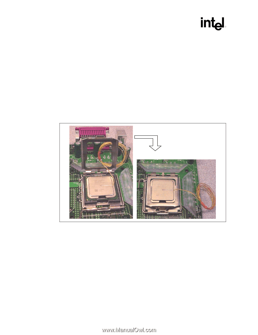
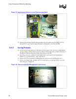
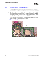
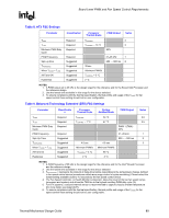
Case Temperature Reference Metrology R D.7 Thermocouple Wire Management When installing the processor into the socket, make sure that the thermocouple wires exit above the load plate as shown in Figure 41. Pinching the thermocouple wires between the load plate and the IHS will likely damage the wires. Note: When thermocouple wires are damaged, the resulting reading maybe incorrect. For example, if there are any cuts into the wires insulation where the wires are pinched between the IHS and the load plate, the thermocouple wires can get in contact with each other at this location. In that case, the reported temperature would be at the edge of the IHS/socket load plate area. This temperature is usually much lower than the temperature at the center of the IHS. Prior to installing the heatsink, make sure that the thermocouple wires remain below the IHS top surface, by running a flat blade on top of the IHS for example. Figure 41. Thermocouple Wire Management § 86 Thermal/Mechanical Design Guide
-
 1
1 -
2
-
3
-
4
-
5
-
6
-
7
-
8
-
9
-
10
-
11
-
12
-
13
-
14
-
15
-
16
-
17
-
18
-
19
-
20
-
21
-
22
-
23
-
24
-
25
-
26
-
27
-
28
-
29
-
30
-
31
-
32
-
33
-
34
-
35
-
36
-
37
-
38
-
39
-
40
-
41
-
42
-
43
-
44
-
45
-
46
-
47
-
48
-
49
-
50
-
51
-
52
-
53
-
54
-
55
-
56
-
57
-
58
-
59
-
60
-
61
-
62
-
63
-
64
-
65
-
66
-
67
-
68
-
69
-
70
-
71
-
72
-
73
-
74
-
75
-
76
-
77
-
78
-
79
-
80
-
 81
81 -
 82
82 -
 83
83 -
 84
84 -
 85
85 -
 86
86 -
 87
87 -
 88
88 -
 89
89 -
 90
90 -
 91
91 -
92
-
93
-
94
-
95
-
96
-
97
-
98
-
99
-
100
-
101
-
102
-
103
-
104
-
105
 |
 |