Intel 640 User Guide - Page 41
Reference Heatsink Thermal Validation, Fan Performance for Active Heatsink Thermal Solution
 |
UPC - 683728178901
View all Intel 640 manuals
Add to My Manuals
Save this manual to your list of manuals |
Page 41 highlights
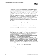
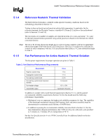
Intel® Thermal/Mechanical Reference Design Information R 5.1.4 Reference Heatsink Thermal Validation The Intel reference heatsink is validated within specific boundary conditions based on the methodology described in Section 5.2. Testing is done on bench top test boards at ambient lab temperature. In particular, for the reference heatsink, the Plexiglas* barrier is installed 81.28 mm [3.2 in] above the motherboard (refer to Sections 3.3 and 5.6). The test results, for a number of samples, are reported in terms of a worst-case mean + 3σ value for thermal characterization parameter using actual processors (based on the thermal test vehicle correction factors). Note: The above 81.28 mm obstruction height that is used for testing complies with the recommended obstruction height of 88.9 mm for the ATX form factor. However, it would not be sufficient for systems in strict compliance with the ATX specification that defines a 76.2 mm obstruction height in Area A. 5.1.5 Fan Performance for Active Heatsink Thermal Solution The fan power requirements for proper operation are given in Table 3. Table 3. Fan Electrical Performance Requirements Requirement Peak fan current draw Average fan current draw Fan start-up current draw Fan start-up current draw maximum duration Fan header voltage Tachometer output Value 1.5 A 1.1 A 2.2 A 1.0 second 12 V ± 10% 2 pulse per revolution In addition to comply with overall thermal requirements (Section 5.1.1), and the general environmental reliability requirements (Section 5.2) the fan should meet the following performance requirements: • Mechanical wear out represents the highest risk reliability parameter for fans. The capability of the functional mechanical elements (ball bearing, shaft, and tower assembly) must be demonstrated to a minimum useful lifetime of 50,000 hours. • In addition to passing the environmental reliability tests described in Section 5.2, the fan must demonstrate adequate performance after 7,500 on/off cycles with each cycle specified as 3 minutes on, 2 minutes off, at a temperature of 70 °C. See the Fan Specification for 4-wire PWM Controlled Fans for additional details on the fan specification. Thermal/Mechanical Design Guide 41
-
 1
1 -
2
-
3
-
4
-
5
-
6
-
7
-
8
-
9
-
10
-
11
-
12
-
13
-
14
-
15
-
16
-
17
-
18
-
19
-
20
-
21
-
22
-
23
-
24
-
25
-
26
-
27
-
28
-
29
-
30
-
31
-
32
-
33
-
34
-
35
-
 36
36 -
 37
37 -
 38
38 -
 39
39 -
 40
40 -
 41
41 -
 42
42 -
 43
43 -
 44
44 -
 45
45 -
 46
46 -
47
-
48
-
49
-
50
-
51
-
52
-
53
-
54
-
55
-
56
-
57
-
58
-
59
-
60
-
61
-
62
-
63
-
64
-
65
-
66
-
67
-
68
-
69
-
70
-
71
-
72
-
73
-
74
-
75
-
76
-
77
-
78
-
79
-
80
-
81
-
82
-
83
-
84
-
85
-
86
-
87
-
88
-
89
-
90
-
91
-
92
-
93
-
94
-
95
-
96
-
97
-
98
-
99
-
100
-
101
-
102
-
103
-
104
-
105
 |
 |