Intel 640 User Guide - Page 6

Intel 640 - Pentium 4 640 3.2GHz 800MHz 2MB Socket 775 CPU Manual

Page 6 highlights

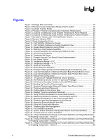
R Figures Figure 1. Package IHS Load Areas 15 Figure 2. Processor Case Temperature Measurement Location 19 Figure 3. Example Thermal Profile 20 Figure 4. Processor Thermal Characterization Parameter Relationships 26 Figure 5. Locations for Measuring Local Ambient Temperature, Active Heatsink 29 Figure 6. Locations for Measuring Local Ambient Temperature, Passive Heatsink......... 29 Figure 7. Concept for Clocks under Thermal Monitor Control 33 Figure 8. Random Vibration PSD 42 Figure 9. Shock Acceleration Curve 43 Figure 10. Intel® RCBFH-3 Reference Design 46 Figure 11. Intel® RCBFH-3 Reference Design (Exploded View 47 Figure 12. Upward Board Deflection during Shock 48 Figure 13. Reference Clip/Heatsink Assembly 49 Figure 14. Critical Parameters for Interfacing to Reference Clip 51 Figure 15. Critical Core Dimension 51 Figure 16. Thermistor Set Points 54 Figure 17. Example Acoustic Fan Speed Control Implementation 55 Figure 18. Fan Speed Control 56 Figure 19. Temperature Range = 5 °C 57 Figure 20. Temperature Range = 10 °C 58 Figure 21. Diode and Thermistor 59 Figure 22. Board Deflection Definition 63 Figure 23. Example: Defining Heatsink Preload Meeting Board Deflection Limit 64 Figure 24. Load Cell Installation in Machined Heatsink Base Pocket (Bottom View) ...... 68 Figure 25. Load Cell Installation in Machined Heatsink Base Pocket (Side View 69 Figure 26. Preload Test Configuration 69 Figure 27. 775-Land LGA Package Reference Groove Drawing 78 Figure 28. IHS Reference Groove on the 775-Land LGA Package 79 Figure 29. IHS Groove Orientation Relative to the LGA775 Socket 79 Figure 30. Bending the Tip of the Thermocouple 80 Figure 31. Securing Thermocouple Wires with Kapton Tape Prior to Attach 81 Figure 32. Thermocouple Bead Placement 81 Figure 33. Position Bead on the Groove Step 82 Figure 34. Detailed Thermocouple Bead Placement 82 Figure 35. Using 3D Micromanipulator to Secure Bead Location 83 Figure 36. Measuring Resistance between Thermocouple and IHS 83 Figure 37. Applying the Adhesive on the Thermocouple Bead 84 Figure 38. Thermocouple Wire Management in the Groove 84 Figure 39. Removing Excess Adhesive from IHS 85 Figure 40. Filling the Groove with Adhesive 85 Figure 41. Thermocouple Wire Management 86 Figure 42. FSC Definitions Example 88 Figure 43. System Airflow Illustration with System Monitor Point Area Identified 92 Figure 44. Thermal Sensor Location Illustration 92 Figure 45. ATX/µATX Motherboard Keep-out Footprint Definition and Height Restrictions for Enabling Components - Sheet 1 94 Figure 46. ATX/µATX Motherboard Keep-out Footprint Definition and Height Restrictions for Enabling Components - Sheet 2 95 Figure 47. ATX/µATX Motherboard Keep-out Footprint Definition and Height Restrictions for Enabling Components - Sheet 3 96 6 Thermal/Mechanical Design Guide

  • 1
  • 2
  • 3
  • 4
  • 5
  • 6
  • 7
  • 8
  • 9
  • 10
  • 11
  • 12
  • 13
  • 14
  • 15
  • 16
  • 17
  • 18
  • 19
  • 20
  • 21
  • 22
  • 23
  • 24
  • 25
  • 26
  • 27
  • 28
  • 29
  • 30
  • 31
  • 32
  • 33
  • 34
  • 35
  • 36
  • 37
  • 38
  • 39
  • 40
  • 41
  • 42
  • 43
  • 44
  • 45
  • 46
  • 47
  • 48
  • 49
  • 50
  • 51
  • 52
  • 53
  • 54
  • 55
  • 56
  • 57
  • 58
  • 59
  • 60
  • 61
  • 62
  • 63
  • 64
  • 65
  • 66
  • 67
  • 68
  • 69
  • 70
  • 71
  • 72
  • 73
  • 74
  • 75
  • 76
  • 77
  • 78
  • 79
  • 80
  • 81
  • 82
  • 83
  • 84
  • 85
  • 86
  • 87
  • 88
  • 89
  • 90
  • 91
  • 92
  • 93
  • 94
  • 95
  • 96
  • 97
  • 98
  • 99
  • 100
  • 101
  • 102
  • 103
  • 104
  • 105

R
6
Thermal/Mechanical Design Guide
Figures
Figure 1. Package IHS Load Areas
..................................................................................
15
Figure 2. Processor Case Temperature Measurement Location
.....................................
19
Figure 3. Example Thermal Profile
...................................................................................
20
Figure 4. Processor Thermal Characterization Parameter Relationships
........................
26
Figure 5. Locations for Measuring Local Ambient Temperature, Active Heatsink
...........
29
Figure 6. Locations for Measuring Local Ambient Temperature, Passive Heatsink
.........
29
Figure 7. Concept for Clocks under Thermal Monitor Control
..........................................
33
Figure 8. Random Vibration PSD
......................................................................................
42
Figure 9. Shock Acceleration Curve
.................................................................................
43
Figure 10. Intel
®
RCBFH-3 Reference Design
..................................................................
46
Figure 11. Intel
®
RCBFH-3 Reference Design (Exploded View)
......................................
47
Figure 12. Upward Board Deflection during Shock
..........................................................
48
Figure 13. Reference Clip/Heatsink Assembly
.................................................................
49
Figure 14. Critical Parameters for Interfacing to Reference Clip
......................................
51
Figure 15. Critical Core Dimension
...................................................................................
51
Figure 16. Thermistor Set Points
......................................................................................
54
Figure 17. Example Acoustic Fan Speed Control Implementation
...................................
55
Figure 18. Fan Speed Control
...........................................................................................
56
Figure 19. Temperature Range = 5 °C
.............................................................................
57
Figure 20. Temperature Range = 10 °C
...........................................................................
58
Figure 21. Diode and Thermistor
......................................................................................
59
Figure 22. Board Deflection Definition
..............................................................................
63
Figure 23. Example: Defining Heatsink Preload Meeting Board Deflection Limit
.............
64
Figure 24. Load Cell Installation in Machined Heatsink Base Pocket (Bottom View)
......
68
Figure 25. Load Cell Installation in Machined Heatsink Base Pocket (Side View)
...........
69
Figure 26. Preload Test Configuration
..............................................................................
69
Figure 27. 775-Land LGA Package Reference Groove Drawing
.....................................
78
Figure 28. IHS Reference Groove on the 775-Land LGA Package
.................................
79
Figure 29. IHS Groove Orientation Relative to the LGA775 Socket
.................................
79
Figure 30. Bending the Tip of the Thermocouple
.............................................................
80
Figure 31. Securing Thermocouple Wires with Kapton Tape Prior to Attach
...................
81
Figure 32. Thermocouple Bead Placement
......................................................................
81
Figure 33. Position Bead on the Groove Step
..................................................................
82
Figure 34. Detailed Thermocouple Bead Placement
........................................................
82
Figure 35. Using 3D Micromanipulator to Secure Bead Location
....................................
83
Figure 36. Measuring Resistance between Thermocouple and IHS
................................
83
Figure 37. Applying the Adhesive on the Thermocouple Bead
........................................
84
Figure 38. Thermocouple Wire Management in the Groove
............................................
84
Figure 39. Removing Excess Adhesive from IHS
.............................................................
85
Figure 40. Filling the Groove with Adhesive
.....................................................................
85
Figure 41. Thermocouple Wire Management
...................................................................
86
Figure 42. FSC Definitions Example
.................................................................................
88
Figure 43. System Airflow Illustration with System Monitor Point Area Identified
............
92
Figure 44. Thermal Sensor Location Illustration
...............................................................
92
Figure 45. ATX/μATX Motherboard Keep-out Footprint Definition and Height Restrictions
for Enabling Components – Sheet 1
..........................................................................
94
Figure 46. ATX/μATX Motherboard Keep-out Footprint Definition and Height Restrictions
for Enabling Components – Sheet 2
..........................................................................
95
Figure 47. ATX/μATX Motherboard Keep-out Footprint Definition and Height Restrictions
for Enabling Components – Sheet 3
..........................................................................
96