Intel 640 User Guide - Page 56
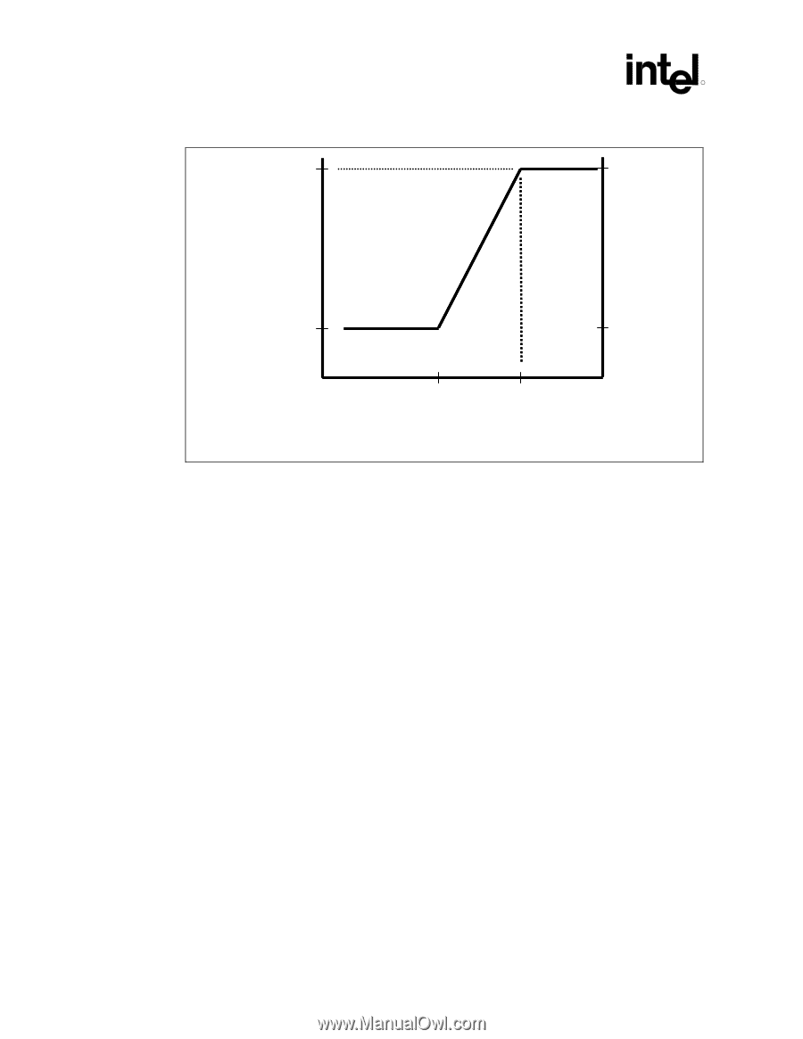
Temperature to begin Fan Acceleration
 |
UPC - 683728178901
View all Intel 640 manuals
Add to My Manuals
Save this manual to your list of manuals |
Page 56 highlights
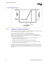
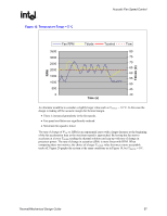
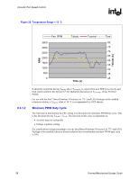
Acoustic Fan Speed Control Figure 18. Fan Speed Control Full Speed R 100 % Fan Speed (RPM) Fan Speed (% PWM Duty Cycle) Min Speed X % TLOW TCONTROL Diode Temperature (°C) 6.3.1.1 Temperature to begin Fan Acceleration The first item to consider is the value for TLOW. The FSC device needs a minimum temperature to set as the threshold to begin increasing PWM duty cycle to the fan. The system designer might initially consider a small temperature range (TCONTROL - TLOW = TRANGE), such as 5 °C to accelerate the fan. That would delay the fan accelerating for the longest period after an increase in TDIODE. There are a number of issues that should be considered with this strategy: • There is little granularity in the fan speeds. For each 1 °C of increase in diode temperature = 20% jump in PWM duty cycle %. • Fan speed oscillation as the thermal solution chases the diode temperature. • Having TDIODE overshoot TCONTROL and the thermal profile causing the Thermal Control Circuit to activate to reduce the temperature. The first two cases can create a poor acoustic response for the user. For the third case, the user could notice a drop in performance as the thermal control circuit reduces the power. Figure 19 is an example of this situation. The system begins at idle and a moderate workload is applied (less than TDP). 56 Thermal/Mechanical Design Guide
-
 1
1 -
2
-
3
-
4
-
5
-
6
-
7
-
8
-
9
-
10
-
11
-
12
-
13
-
14
-
15
-
16
-
17
-
18
-
19
-
20
-
21
-
22
-
23
-
24
-
25
-
26
-
27
-
28
-
29
-
30
-
31
-
32
-
33
-
34
-
35
-
36
-
37
-
38
-
39
-
40
-
41
-
42
-
43
-
44
-
45
-
46
-
47
-
48
-
49
-
50
-
 51
51 -
 52
52 -
 53
53 -
 54
54 -
 55
55 -
 56
56 -
 57
57 -
 58
58 -
 59
59 -
 60
60 -
 61
61 -
62
-
63
-
64
-
65
-
66
-
67
-
68
-
69
-
70
-
71
-
72
-
73
-
74
-
75
-
76
-
77
-
78
-
79
-
80
-
81
-
82
-
83
-
84
-
85
-
86
-
87
-
88
-
89
-
90
-
91
-
92
-
93
-
94
-
95
-
96
-
97
-
98
-
99
-
100
-
101
-
102
-
103
-
104
-
105
 |
 |