Intel 640 User Guide - Page 49
Mechanical Interface to the Reference Attach Mechanism
 |
UPC - 683728178901
View all Intel 640 manuals
Add to My Manuals
Save this manual to your list of manuals |
Page 49 highlights
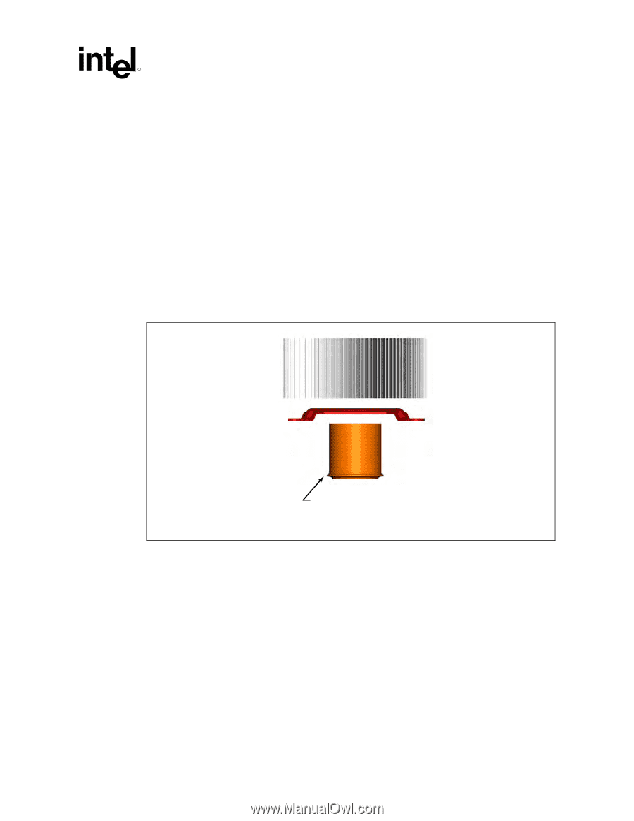
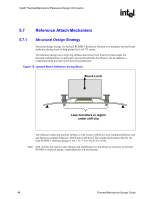
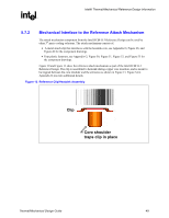
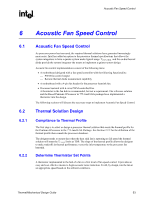
Intel® Thermal/Mechanical Reference Design Information R 5.7.2 Mechanical Interface to the Reference Attach Mechanism The attach mechanism component from the Intel RCBFH-3 Reference Design can be used by other 3rd party cooling solutions. The attach mechanism consists of: • A metal attach clip that interfaces with the heatsink core, see Appendix G, Figure 48, and Figure 49 for the component drawings. • Four plastic fasteners, see Appendix G, Figure 50, Figure 51, Figure 52, and Figure 53 for the component drawings. Figure 10 and Figure 11 show the reference attach mechanism as part of the Intel RCBFH-3 Reference Design. The clip is assembled to heatsink during copper core insertion, and is meant to be trapped between the core shoulder and the extrusion as shown in Figure 13. Figure 54 in Appendix G provides additional details. Figure 13. Reference Clip/Heatsink Assembly Clip Core shoulder traps clip in place Thermal/Mechanical Design Guide 49
-
 1
1 -
2
-
3
-
4
-
5
-
6
-
7
-
8
-
9
-
10
-
11
-
12
-
13
-
14
-
15
-
16
-
17
-
18
-
19
-
20
-
21
-
22
-
23
-
24
-
25
-
26
-
27
-
28
-
29
-
30
-
31
-
32
-
33
-
34
-
35
-
36
-
37
-
38
-
39
-
40
-
41
-
42
-
43
-
 44
44 -
 45
45 -
 46
46 -
 47
47 -
 48
48 -
 49
49 -
 50
50 -
 51
51 -
 52
52 -
 53
53 -
 54
54 -
55
-
56
-
57
-
58
-
59
-
60
-
61
-
62
-
63
-
64
-
65
-
66
-
67
-
68
-
69
-
70
-
71
-
72
-
73
-
74
-
75
-
76
-
77
-
78
-
79
-
80
-
81
-
82
-
83
-
84
-
85
-
86
-
87
-
88
-
89
-
90
-
91
-
92
-
93
-
94
-
95
-
96
-
97
-
98
-
99
-
100
-
101
-
102
-
103
-
104
-
105
 |
 |