Intel 640 User Guide - Page 53
Acoustic Fan Speed Control
 |
UPC - 683728178901
View all Intel 640 manuals
Add to My Manuals
Save this manual to your list of manuals |
Page 53 highlights
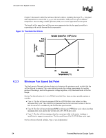
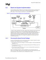
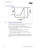
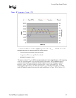
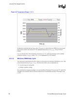
Acoustic Fan Speed Control R 6 Acoustic Fan Speed Control 6.1 6.2 6.2.1 6.2.2 Acoustic Fan Speed Control As processor power has increased, the required thermal solutions have generated increasingly more noise. Intel has added an option to the processor thermal specifications that allows the system integrators to have a quieter system under typical usage. TCONTROL and the on-die thermal diode provide the system integrator the means to implement a quieter system design. Acoustic fan control implementations consist of the following items • A motherboard designed with a fan speed controller with the following functionality: ⎯ PWM fan control output ⎯ Remote thermal diode measurement capability • A motherboard with a 4-pin fan header for the processor heatsink fan. • Processor heatsink with 4-wire PWM controlled Fan. A thermistor in the fan hub is recommended, but not a requirement. The reference solution and the Boxed Pentium 4 Processor in 775-land LGA package have implemented a thermistor into the design. The following sections will discuss the necessary steps to implement Acoustic Fan Speed Control. Thermal Solution Design Compliance to Thermal Profile The first step is to select or design a processor thermal solution that meets the thermal profile for the Pentium 4 Processor in the 775-land LGA Package. See Section 2.2.2 for the definition of the thermal profile then consult the processor datasheet. The designer needs to ensure that when the heat sink fan is operating at full speed the thermal solution will meet the TC-MAX limits at TDP. The slope of the thermal profile allows the designer to make tradeoffs in thermal performance versus the inlet temperature to the processor fan heatsink. Determine Thermistor Set Points A thermistor implemented in the hub of a fan is a first level of fan speed control. It provides an easy and cost effective means to begin acoustic noise reduction. It will, by design, run the fan at an appropriate speed based on the ambient conditions. Thermal/Mechanical Design Guide 53
-
 1
1 -
2
-
3
-
4
-
5
-
6
-
7
-
8
-
9
-
10
-
11
-
12
-
13
-
14
-
15
-
16
-
17
-
18
-
19
-
20
-
21
-
22
-
23
-
24
-
25
-
26
-
27
-
28
-
29
-
30
-
31
-
32
-
33
-
34
-
35
-
36
-
37
-
38
-
39
-
40
-
41
-
42
-
43
-
44
-
45
-
46
-
47
-
 48
48 -
 49
49 -
 50
50 -
 51
51 -
 52
52 -
 53
53 -
 54
54 -
 55
55 -
 56
56 -
 57
57 -
 58
58 -
59
-
60
-
61
-
62
-
63
-
64
-
65
-
66
-
67
-
68
-
69
-
70
-
71
-
72
-
73
-
74
-
75
-
76
-
77
-
78
-
79
-
80
-
81
-
82
-
83
-
84
-
85
-
86
-
87
-
88
-
89
-
90
-
91
-
92
-
93
-
94
-
95
-
96
-
97
-
98
-
99
-
100
-
101
-
102
-
103
-
104
-
105
 |
 |