Intel 640 User Guide - Page 24
System Integration Considerations
 |
UPC - 683728178901
View all Intel 640 manuals
Add to My Manuals
Save this manual to your list of manuals |
Page 24 highlights
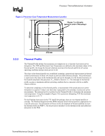
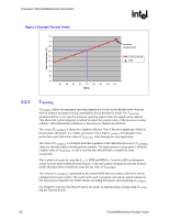
Processor Thermal/Mechanical Information R 2.4.3 2.5 To ease the burden on thermal solutions, the Thermal Monitor feature and associated logic have been integrated into the silicon of the Pentium 4 processor in the 775-land LGA package. By taking advantage of the Thermal Monitor feature, system designers may reduce thermal solution cost by designing to TDP instead of maximum power. Thermal Monitor attempts to protect the processor during sustained workload above TDP. Implementation options and recommendations are described in Chapter 4. Summary In summary, considerations in heatsink design include: • The local ambient temperature TA at the heatsink, which is a function of chassis design. • The thermal design power (TDP) of the processor, and the corresponding maximum TC as calculated from the thermal profile. These parameters are usually combined in a single cooling performance parameter, ΨCA (case to air thermal characterization parameter). More information on the definition and the use of ΨCA is given Section 3.1. • Heatsink interface to IHS surface characteristics, including flatness and roughness. • The performance of the thermal interface material used between the heatsink and the IHS. • The required heatsink clip static load, between 18 lbf to 70 lbf throughout the life of the product (Refer to Section 2.1.2.2 for further information). • Surface area of the heatsink. • Heatsink material and technology. • Volume of airflow over the heatsink surface area. • Development of airflow entering and within the heatsink area. • Physical volumetric constraints placed by the system System Integration Considerations Boxed Intel® Pentium® 4 Processor in the 775-Land LGA Package - Integration Video provides best known methods for package and heatsink installation and removal for LGA775 socket based platforms and systems manufacturing. The video is available on the Web, from http://www.intel.com/go/integration. § 24 Thermal/Mechanical Design Guide
-
 1
1 -
2
-
3
-
4
-
5
-
6
-
7
-
8
-
9
-
10
-
11
-
12
-
13
-
14
-
15
-
16
-
17
-
18
-
 19
19 -
 20
20 -
 21
21 -
 22
22 -
 23
23 -
 24
24 -
 25
25 -
 26
26 -
 27
27 -
 28
28 -
 29
29 -
30
-
31
-
32
-
33
-
34
-
35
-
36
-
37
-
38
-
39
-
40
-
41
-
42
-
43
-
44
-
45
-
46
-
47
-
48
-
49
-
50
-
51
-
52
-
53
-
54
-
55
-
56
-
57
-
58
-
59
-
60
-
61
-
62
-
63
-
64
-
65
-
66
-
67
-
68
-
69
-
70
-
71
-
72
-
73
-
74
-
75
-
76
-
77
-
78
-
79
-
80
-
81
-
82
-
83
-
84
-
85
-
86
-
87
-
88
-
89
-
90
-
91
-
92
-
93
-
94
-
95
-
96
-
97
-
98
-
99
-
100
-
101
-
102
-
103
-
104
-
105
 |
 |