Intel 640 User Guide - Page 26
Example
 |
UPC - 683728178901
View all Intel 640 manuals
Add to My Manuals
Save this manual to your list of manuals |
Page 26 highlights
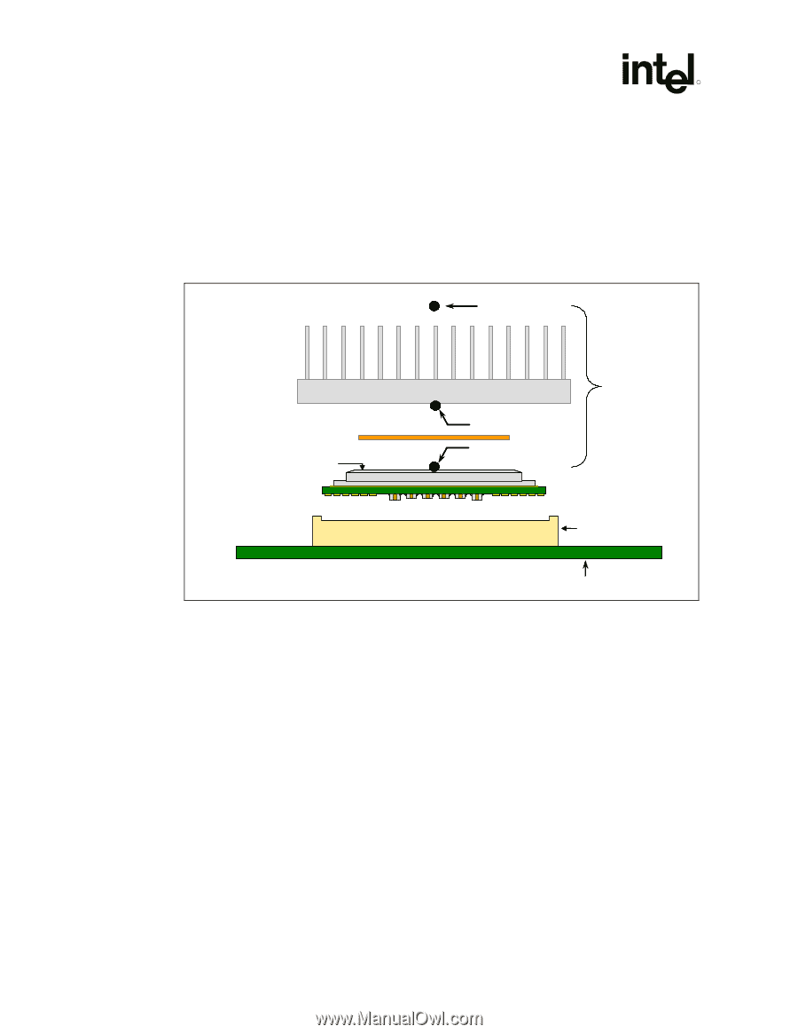
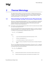
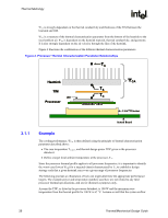
Thermal Metrology R ΨCS is strongly dependent on the thermal conductivity and thickness of the TIM between the heatsink and IHS. ΨSA is a measure of the thermal characterization parameter from the bottom of the heatsink to the local ambient air. ΨSA is dependent on the heatsink material, thermal conductivity, and geometry. It is also strongly dependent on the air velocity through the fins of the heatsink. Figure 4 illustrates the combination of the different thermal characterization parameters. Figure 4. Processor Thermal Characterization Parameter Relationships TA Heatsink TIM IHS Processor ΨCA TS TC LGA775 Socket 3.1.1 System Board Example The cooling performance, ΨCA, is then defined using the principle of thermal characterization parameter described above: • The case temperature TC-MAX and thermal design power TDP given in the processor datasheet. • Define a target local ambient temperature at the processor, TA. Since the processor thermal profile applies to all processor frequencies, it is important to identify the worst case (lowest ΨCA) for a targeted chassis characterized by TA to establish a design strategy such that a given heatsink can cover a given range of processor frequencies. The following provides an illustration of how one might determine the appropriate performance targets. The example power and temperature numbers used here are not related to any Intel processor thermal specifications, and are for illustrative purposes only. Assume the TDP, as listed in the processor datasheet, is 100 W and the maximum case temperature from the thermal profile for 100 W is 67 °C. Assume as well that the system airflow 26 Thermal/Mechanical Design Guide
-
 1
1 -
2
-
3
-
4
-
5
-
6
-
7
-
8
-
9
-
10
-
11
-
12
-
13
-
14
-
15
-
16
-
17
-
18
-
19
-
20
-
 21
21 -
 22
22 -
 23
23 -
 24
24 -
 25
25 -
 26
26 -
 27
27 -
 28
28 -
 29
29 -
 30
30 -
 31
31 -
32
-
33
-
34
-
35
-
36
-
37
-
38
-
39
-
40
-
41
-
42
-
43
-
44
-
45
-
46
-
47
-
48
-
49
-
50
-
51
-
52
-
53
-
54
-
55
-
56
-
57
-
58
-
59
-
60
-
61
-
62
-
63
-
64
-
65
-
66
-
67
-
68
-
69
-
70
-
71
-
72
-
73
-
74
-
75
-
76
-
77
-
78
-
79
-
80
-
81
-
82
-
83
-
84
-
85
-
86
-
87
-
88
-
89
-
90
-
91
-
92
-
93
-
94
-
95
-
96
-
97
-
98
-
99
-
100
-
101
-
102
-
103
-
104
-
105
 |
 |