Intel 640 User Guide - Page 17
Heatsink Attach
 |
UPC - 683728178901
View all Intel 640 manuals
Add to My Manuals
Save this manual to your list of manuals |
Page 17 highlights
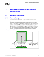
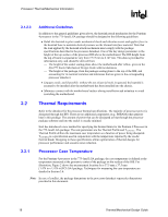
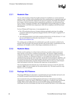
Processor Thermal/Mechanical Information R 2.1.2 Heatsink Attach 2.1.2.1 General Guidelines There are no features on the LGA775 socket to directly attach a heatsink; a mechanism must be designed to attach the heatsink directly to the motherboard. In addition to holding the heatsink in place on top of the IHS, this mechanism plays a significant role in the robustness of the system in which it is implemented, in particular: • Ensuring thermal performance of the thermal interface material (TIM) applied between the IHS and the heatsink. TIMs based on phase change materials are very sensitive to applied pressure: the higher the pressure, the better the initial performance. TIMs (such as thermal greases) are not as sensitive to applied pressure. Designs should consider a possible decrease in applied pressure over time due to potential structural relaxation in retention components. • Ensuring system electrical, thermal, and structural integrity under shock and vibration events. The mechanical requirements of the heatsink attach mechanism depend on the mass of the heatsink and the level of shock and vibration that the system must support. The overall structural design of the motherboard and the system have to be considered when designing the heatsink attach mechanism. Their design should provide a means for protecting LGA775 socket solder joints. One of the strategies for mechanical protection of the socket is to use a preload and high stiffness clip. This strategy is implemented by the reference design and described in Section 5.7. Note: Package pull-out during mechanical shock and vibration is constrained by the LGA775 socket load plate (refer to the LGA775 Socket Mechanical Design Guide for further information). 2.1.2.2 Heatsink Clip Load Requirement The attach mechanism for the heatsink developed to support the Pentium 4 processor in the 775-land LGA package should create a static preload on the package between 18 lbf and 70 lbf throughout the life of the product for designs compliant with the Intel reference design assumptions: • 72 mm x 72 mm mounting hole span (refer to Figure 45) • And no board stiffening device (backing plate, chassis attach, etc.). The minimum load is required to protect against fatigue failure of socket solder joint in temperature cycling. It is important to take into account potential load degradation from creep over time when designing the clip and fastener to the required minimum load. This means that, depending on clip stiffness, the initial preload at beginning of life of the product may be significantly higher than the minimum preload that must be met throughout the life of the product. For additional guidelines on mechanical design, in particular on designs departing from the reference design assumptions refer to Appendix A. For clip load metrology guidelines, refer to Appendix B. Thermal/Mechanical Design Guide 17
-
 1
1 -
2
-
3
-
4
-
5
-
6
-
7
-
8
-
9
-
10
-
11
-
 12
12 -
 13
13 -
 14
14 -
 15
15 -
 16
16 -
 17
17 -
 18
18 -
 19
19 -
 20
20 -
 21
21 -
 22
22 -
23
-
24
-
25
-
26
-
27
-
28
-
29
-
30
-
31
-
32
-
33
-
34
-
35
-
36
-
37
-
38
-
39
-
40
-
41
-
42
-
43
-
44
-
45
-
46
-
47
-
48
-
49
-
50
-
51
-
52
-
53
-
54
-
55
-
56
-
57
-
58
-
59
-
60
-
61
-
62
-
63
-
64
-
65
-
66
-
67
-
68
-
69
-
70
-
71
-
72
-
73
-
74
-
75
-
76
-
77
-
78
-
79
-
80
-
81
-
82
-
83
-
84
-
85
-
86
-
87
-
88
-
89
-
90
-
91
-
92
-
93
-
94
-
95
-
96
-
97
-
98
-
99
-
100
-
101
-
102
-
103
-
104
-
105
 |
 |