Intel 640 User Guide - Page 22
Heatsink Size, Heatsink Mass, Package IHS Flatness
 |
UPC - 683728178901
View all Intel 640 manuals
Add to My Manuals
Save this manual to your list of manuals |
Page 22 highlights
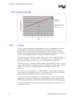
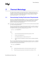
Processor Thermal/Mechanical Information R 2.3.1 2.3.2 2.3.3 Heatsink Size The size of the heatsink is dictated by height restrictions for installation in a system and by the amount of space available on the motherboard and other considerations for component height and placement in the area potentially impacted by the processor heatsink. The height of the heatsink must comply with the requirements and recommendations published for the motherboard form factor of interest. Designing a heatsink to the recommendations may preclude using it in systems adhering strictly to the form factor requirements, while still in compliance with the form factor documentation. For the ATX/microATX form factor, it is recommended to use: • The ATX motherboard keep-out footprint definition and height restrictions for enabling components, defined for the platforms designed with the LGA775 socket in Appendix G of this design guide. • The motherboard primary side height constraints defined in the ATX Specification V2.1 and the microATX Motherboard Interface Specification V1.1 found at http://www.formfactors.org/. The resulting space available above the motherboard is generally not entirely available for the heatsink. The target height of the heatsink must take into account airflow considerations (for fan performance for example) as well as other design considerations (air duct, etc.). Heatsink Mass With the need for pushing air cooling to better performance, heatsink solutions tend to grow larger (increase in fin surface) resulting in increased mass. The insertion of highly thermally conductive materials like copper to increase heatsink thermal conduction performance results in even heavier solutions. As mentioned in Section 2.1, the heatsink mass must take into consideration the package and socket load limits, the heatsink attach mechanical capabilities, and the mechanical shock and vibration profile targets. Beyond a certain heatsink mass, the cost of developing and implementing a heatsink attach mechanism that can ensure the system integrity under the mechanical shock and vibration profile targets may become prohibitive. The recommended maximum heatsink mass for the Pentium 4 processor in the 775-land LGA package is 450g. This mass includes the fan and the heatsink only. The attach mechanism (clip, fasteners, etc.) is not included. Package IHS Flatness The package IHS flatness for the product is specified in the processor datasheet and can be used as a baseline to predict heatsink performance during the design phase. Intel recommends testing and validating heatsink performance in full mechanical enabling configuration to capture any impact of IHS flatness change due to combined socket and heatsink loading. While socket loading alone may increase the IHS warpage, the heatsink preload redistributes the load on the package and improves the resulting IHS flatness in the enabled state. 22 Thermal/Mechanical Design Guide
-
 1
1 -
2
-
3
-
4
-
5
-
6
-
7
-
8
-
9
-
10
-
11
-
12
-
13
-
14
-
15
-
16
-
 17
17 -
 18
18 -
 19
19 -
 20
20 -
 21
21 -
 22
22 -
 23
23 -
 24
24 -
 25
25 -
 26
26 -
 27
27 -
28
-
29
-
30
-
31
-
32
-
33
-
34
-
35
-
36
-
37
-
38
-
39
-
40
-
41
-
42
-
43
-
44
-
45
-
46
-
47
-
48
-
49
-
50
-
51
-
52
-
53
-
54
-
55
-
56
-
57
-
58
-
59
-
60
-
61
-
62
-
63
-
64
-
65
-
66
-
67
-
68
-
69
-
70
-
71
-
72
-
73
-
74
-
75
-
76
-
77
-
78
-
79
-
80
-
81
-
82
-
83
-
84
-
85
-
86
-
87
-
88
-
89
-
90
-
91
-
92
-
93
-
94
-
95
-
96
-
97
-
98
-
99
-
100
-
101
-
102
-
103
-
104
-
105
 |
 |