Intel 640 User Guide - Page 18
Thermal Requirements
 |
UPC - 683728178901
View all Intel 640 manuals
Add to My Manuals
Save this manual to your list of manuals |
Page 18 highlights
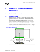
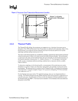
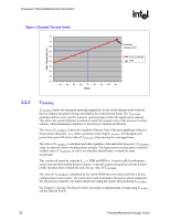
Processor Thermal/Mechanical Information R 2.1.2.3 Additional Guidelines In addition to the general guidelines given above, the heatsink attach mechanism for the Pentium 4 processor in the 775-land LGA package should be designed to the following guidelines: • Holds the heatsink in place under mechanical shock and vibration events and applies force to the heatsink base to maintain desired pressure on the thermal interface material. Note that the load applied by the heatsink attach mechanism must comply with the package specifications described in the processor datasheet. One of the key design parameters is the height of the top surface of the processor IHS above the motherboard. The IHS height from the top of board is expected to vary from 7.517 mm to 8.167 mm. This data is provided for information only, and should be derived from: ⎯ The height of the socket seating plane above the motherboard after reflow, given in the LGA775 Socket Mechanical Design Guide with its tolerances ⎯ The height of the package, from the package seating plane to the top of the IHS, and accounting for its nominal variation and tolerances that are given in the corresponding processor datasheet. • Engages easily, and if possible, without the use of special tools. In general, the heatsink is assumed to be installed after the motherboard has been installed into the chassis. • Minimizes contact with the motherboard surface during installation and actuation to avoid scratching the motherboard. 2.2 Thermal Requirements Refer to the datasheet for the processor thermal specifications. The majority of processor power is dissipated through the IHS. There are no additional components (e.g., BSRAMs) that generate heat in this package. The amount of power that can be dissipated as heat through the processor package substrate and into the socket is usually minimal. Intel has introduced a new method for specifying the thermal limits for the Pentium 4 Processor in the 775-land LGA package. The new parameters are the Thermal Profile and TCONTROL. The Thermal Profile defines the maximum case temperature as a function of power being dissipated. TCONTROL is a specification used in conjunction with the temperature reported by the on-die thermal diode. Designing to these specifications allows optimization of thermal designs for processor performance and acoustic noise reduction. 2.2.1 Processor Case Temperature For the Pentium 4 processor in the 775-land LGA package, the case temperature is defined as the temperature measured at the geometric center of the package on the surface of the IHS. For illustration, Figure 2 shows the measurement location for a 37.5 mm x 37.5 mm [1.474 in x 1.474 in] FCLGA4 package. Techniques for measuring the case temperature are detailed in Section 3.4. Note: In case of conflict, the package dimensions in the processor datasheet supersedes dimensions provided in this document. 18 Thermal/Mechanical Design Guide
-
 1
1 -
2
-
3
-
4
-
5
-
6
-
7
-
8
-
9
-
10
-
11
-
12
-
 13
13 -
 14
14 -
 15
15 -
 16
16 -
 17
17 -
 18
18 -
 19
19 -
 20
20 -
 21
21 -
 22
22 -
 23
23 -
24
-
25
-
26
-
27
-
28
-
29
-
30
-
31
-
32
-
33
-
34
-
35
-
36
-
37
-
38
-
39
-
40
-
41
-
42
-
43
-
44
-
45
-
46
-
47
-
48
-
49
-
50
-
51
-
52
-
53
-
54
-
55
-
56
-
57
-
58
-
59
-
60
-
61
-
62
-
63
-
64
-
65
-
66
-
67
-
68
-
69
-
70
-
71
-
72
-
73
-
74
-
75
-
76
-
77
-
78
-
79
-
80
-
81
-
82
-
83
-
84
-
85
-
86
-
87
-
88
-
89
-
90
-
91
-
92
-
93
-
94
-
95
-
96
-
97
-
98
-
99
-
100
-
101
-
102
-
103
-
104
-
105
 |
 |