Intel 640 User Guide - Page 54
Minimum Fan Speed Set Point
 |
UPC - 683728178901
View all Intel 640 manuals
Add to My Manuals
Save this manual to your list of manuals |
Page 54 highlights
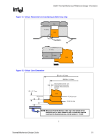
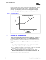
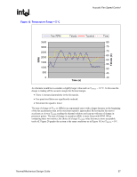
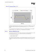
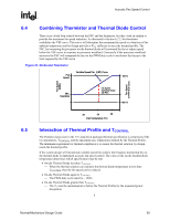
Acoustic Fan Speed Control R Chapter 5 discussed in detail the reference thermal solution, including the target ΨCA, fan speed and temperatures to ensure that TC-MAX is not exceeded for TDP power at a given ambient temperature. The resulting variable speed fan (VSF) curve is the upper limit on fan speed. The benefit of this upper limit will become more apparent when the fan speed controller is responding to the on-die thermal diode temperatures. Figure 16. Thermistor Set Points Full Speed Variable Speed Fan (VSF) Curve Fan Speed (RPM) Min. Operating 6.2.3 30 38 Fan Inlet Temperature (°C) Minimum Fan Speed Set Point The final aspect of thermal solution design is to determine the minimum speed at which the fan will be allowed to operate. This value can be driven by the cooling requirements for another portion of the design, such as the processor voltage regulator, or by functional limits of the fan design. Per the Fan Specification for 4 wire PWM Controlled Fans, there are three possible options to consider: • Type A: The fan will run at minimum RPM for all PWM duty cycle values less than minimum duty cycle. This would be programmed into the fan controller located on the fan hub. It can not be overridden by the external fan speed control. • Type B: The fan will run at minimum RPM for all non-zero PWM duty cycle values less than minimum duty cycle and the fan will turn off at 0% PWM duty cycle. • Type C: The fan will stop running when the current provided to the motor windings is insufficient to support commutation. The fan would turn off at 0% PWM duty cycle input. For the reference thermal solution, Type A was implemented. 54 Thermal/Mechanical Design Guide
-
 1
1 -
2
-
3
-
4
-
5
-
6
-
7
-
8
-
9
-
10
-
11
-
12
-
13
-
14
-
15
-
16
-
17
-
18
-
19
-
20
-
21
-
22
-
23
-
24
-
25
-
26
-
27
-
28
-
29
-
30
-
31
-
32
-
33
-
34
-
35
-
36
-
37
-
38
-
39
-
40
-
41
-
42
-
43
-
44
-
45
-
46
-
47
-
48
-
 49
49 -
 50
50 -
 51
51 -
 52
52 -
 53
53 -
 54
54 -
 55
55 -
 56
56 -
 57
57 -
 58
58 -
 59
59 -
60
-
61
-
62
-
63
-
64
-
65
-
66
-
67
-
68
-
69
-
70
-
71
-
72
-
73
-
74
-
75
-
76
-
77
-
78
-
79
-
80
-
81
-
82
-
83
-
84
-
85
-
86
-
87
-
88
-
89
-
90
-
91
-
92
-
93
-
94
-
95
-
96
-
97
-
98
-
99
-
100
-
101
-
102
-
103
-
104
-
105
 |
 |
