Intel 640 User Guide - Page 55
Board and System Implementation
 |
UPC - 683728178901
View all Intel 640 manuals
Add to My Manuals
Save this manual to your list of manuals |
Page 55 highlights
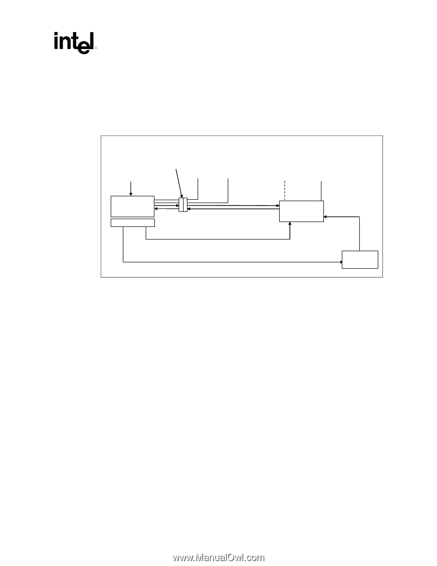
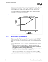
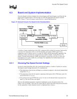
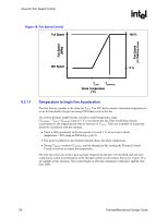
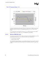
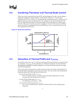
Acoustic Fan Speed Control R 6.3 Board and System Implementation Once the thermal solution is defined, the system designer and board designer can define the fan speed control implementation. The first step is to select the appropriate fan speed controller (FSC). Figure 17 shows the major connections for a typical implementation. Figure 17. Example Acoustic Fan Speed Control Implementation 4-Pin Fan Inlet Ambient Header (Thermistor) GND +12V Sys Ambient (Opt) Sys Fan 4wire PWM (2x) HS Fan Processor Tachometer Pulse Width Modulation (PWM) Fan Speed Controller Thermal Diode (2 wires) TCONTROL BIOS A number of major manufacturers have FSC components that include the necessary functionality to measure the temperature of the on-die thermal diode and output a PWM signal. These components can be a discrete device or a super I/O (SIO) with the functionality embedded. The following vendors currently have components that could be suitable: Analog Devices, ITE, Maxim, National Semiconductor, SMSC and Winbond. Consult their web sites or local sales representatives for a part suitable for your design. See Appendix E for further details on the motherboard requirements 6.3.1 Choosing Fan Speed Control Settings Fan speed control algorithms allow the system thermal engineer a number of options to consider. The typical control settings that need to be considered are: • The temperature when the fan will begin to accelerate in response to the on-die thermal diode temperature (TLOW) • The temperature where the fan speed is operating at full speed (100% PWM duty cycle). By specification this is TCONTROL • The minimum fan speed (PWM duty cycle). For any on-die thermal diode temperature less than TLOW the fan will run at this speed These are the minimum parameters required to implement acoustic fan speed control. See Figure 18 for an example. There may be vendor specific options that offer enhanced functionality. See the appropriate vendor datasheet on how to implement those features. Thermal/Mechanical Design Guide 55
-
 1
1 -
2
-
3
-
4
-
5
-
6
-
7
-
8
-
9
-
10
-
11
-
12
-
13
-
14
-
15
-
16
-
17
-
18
-
19
-
20
-
21
-
22
-
23
-
24
-
25
-
26
-
27
-
28
-
29
-
30
-
31
-
32
-
33
-
34
-
35
-
36
-
37
-
38
-
39
-
40
-
41
-
42
-
43
-
44
-
45
-
46
-
47
-
48
-
49
-
 50
50 -
 51
51 -
 52
52 -
 53
53 -
 54
54 -
 55
55 -
 56
56 -
 57
57 -
 58
58 -
 59
59 -
 60
60 -
61
-
62
-
63
-
64
-
65
-
66
-
67
-
68
-
69
-
70
-
71
-
72
-
73
-
74
-
75
-
76
-
77
-
78
-
79
-
80
-
81
-
82
-
83
-
84
-
85
-
86
-
87
-
88
-
89
-
90
-
91
-
92
-
93
-
94
-
95
-
96
-
97
-
98
-
99
-
100
-
101
-
102
-
103
-
104
-
105
 |
 |