Intel 640 User Guide - Page 80
Thermocouple Attach Procedure
 |
UPC - 683728178901
View all Intel 640 manuals
Add to My Manuals
Save this manual to your list of manuals |
Page 80 highlights
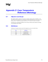
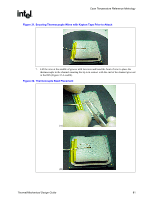
Case Temperature Reference Metrology R D.6 Thermocouple Attach Procedure D.6.1 Thermocouple Conditioning and Preparation 1. Use a calibrated thermocouple as specified in Sections D.3 and D.4. 2. Measure the thermocouple resistance by holding both wires on one probe and the tip of thermocouple to the other probe of the DMM (measurement should be about~75 ohms for 40-gauge type T thermocouple). 3. Straighten the wire for about 38 mm [1 ½ inch] from the bead to place it inside the channel. 4. Bend the tip of the thermocouple at approximately 45 degree angle by about 0.8 mm [0.030 inch] from the tip (Figure 30). Figure 30. Bending the Tip of the Thermocouple D.6.2 Thermocouple Attachment to the IHS 5. Clean groove with IPA and a lint free cloth removing all residues prior to thermocouple attachment. 6. Place the thermocouple wire inside the groove; letting the exposed wire and bead extend about 3.2 mm [0.125 inch] past the end of groove. Secure it with Kapton tape (Figure 31). 80 Thermal/Mechanical Design Guide
-
 1
1 -
2
-
3
-
4
-
5
-
6
-
7
-
8
-
9
-
10
-
11
-
12
-
13
-
14
-
15
-
16
-
17
-
18
-
19
-
20
-
21
-
22
-
23
-
24
-
25
-
26
-
27
-
28
-
29
-
30
-
31
-
32
-
33
-
34
-
35
-
36
-
37
-
38
-
39
-
40
-
41
-
42
-
43
-
44
-
45
-
46
-
47
-
48
-
49
-
50
-
51
-
52
-
53
-
54
-
55
-
56
-
57
-
58
-
59
-
60
-
61
-
62
-
63
-
64
-
65
-
66
-
67
-
68
-
69
-
70
-
71
-
72
-
73
-
74
-
 75
75 -
 76
76 -
 77
77 -
 78
78 -
 79
79 -
 80
80 -
 81
81 -
 82
82 -
 83
83 -
 84
84 -
 85
85 -
86
-
87
-
88
-
89
-
90
-
91
-
92
-
93
-
94
-
95
-
96
-
97
-
98
-
99
-
100
-
101
-
102
-
103
-
104
-
105
 |
 |