Intel 640 User Guide - Page 82
Position Bead on the Groove Step, Detailed Thermocouple Bead Placement
 |
UPC - 683728178901
View all Intel 640 manuals
Add to My Manuals
Save this manual to your list of manuals |
Page 82 highlights
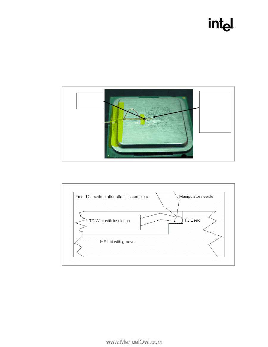
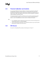
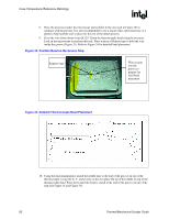
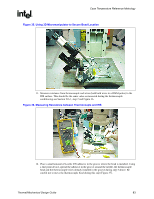
Case Temperature Reference Metrology R 8. Place the processor under the microscope unit (similar to the one used in Figure 36) to continue with the process. It is also recommended to use a fixture (like a processor tray or a plate) to help hold the unit in place for the rest of the attach process. 9. Press the wire down about 6 mm [0.125"] from the thermocouple bead using the tweezers. Look in the microscope to perform this task. Place a piece of Kapton tape to hold the wire inside the groove (Figure 33). Refer to Figure 34 for detailed bead placement. Figure 33. Position Bead on the Groove Step Kapton* tape Wire section into the groove to prepare for final bead placement Figure 34. Detailed Thermocouple Bead Placement 10. Using the micromanipulator, install the needle near to the end of the groove on top of the thermocouple. Using the X, Y, and Z axes on the arm place the tip of the needle on top of the thermocouple bead. Press down until the bead is seated at the end of the groove on top of the step (see Figure 34 and Figure 35). 82 Thermal/Mechanical Design Guide
-
 1
1 -
2
-
3
-
4
-
5
-
6
-
7
-
8
-
9
-
10
-
11
-
12
-
13
-
14
-
15
-
16
-
17
-
18
-
19
-
20
-
21
-
22
-
23
-
24
-
25
-
26
-
27
-
28
-
29
-
30
-
31
-
32
-
33
-
34
-
35
-
36
-
37
-
38
-
39
-
40
-
41
-
42
-
43
-
44
-
45
-
46
-
47
-
48
-
49
-
50
-
51
-
52
-
53
-
54
-
55
-
56
-
57
-
58
-
59
-
60
-
61
-
62
-
63
-
64
-
65
-
66
-
67
-
68
-
69
-
70
-
71
-
72
-
73
-
74
-
75
-
76
-
 77
77 -
 78
78 -
 79
79 -
 80
80 -
 81
81 -
 82
82 -
 83
83 -
 84
84 -
 85
85 -
 86
86 -
 87
87 -
88
-
89
-
90
-
91
-
92
-
93
-
94
-
95
-
96
-
97
-
98
-
99
-
100
-
101
-
102
-
103
-
104
-
105
 |
 |