Intel 640 User Guide - Page 69
Load Cell Installation in Machined Heatsink Base Pocket Side View, Preload
 |
UPC - 683728178901
View all Intel 640 manuals
Add to My Manuals
Save this manual to your list of manuals |
Page 69 highlights
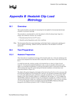
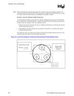
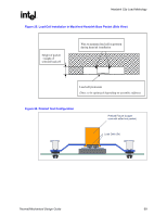
Heatsink Clip Load Metrology R Figure 25. Load Cell Installation in Machined Heatsink Base Pocket (Side View) Height of pocket ~ height of selected load cell Wax to maintain load cell in position during heatsink installation Load cell protrusion (Note: to be optimized depending on assembly stiffness) Figure 26. Preload Test Configuration Preload Fixture (copper core with milled out pocket) Load Cells (3x) Thermal/Mechanical Design Guide 69
-
 1
1 -
2
-
3
-
4
-
5
-
6
-
7
-
8
-
9
-
10
-
11
-
12
-
13
-
14
-
15
-
16
-
17
-
18
-
19
-
20
-
21
-
22
-
23
-
24
-
25
-
26
-
27
-
28
-
29
-
30
-
31
-
32
-
33
-
34
-
35
-
36
-
37
-
38
-
39
-
40
-
41
-
42
-
43
-
44
-
45
-
46
-
47
-
48
-
49
-
50
-
51
-
52
-
53
-
54
-
55
-
56
-
57
-
58
-
59
-
60
-
61
-
62
-
63
-
 64
64 -
 65
65 -
 66
66 -
 67
67 -
 68
68 -
 69
69 -
 70
70 -
 71
71 -
 72
72 -
 73
73 -
 74
74 -
75
-
76
-
77
-
78
-
79
-
80
-
81
-
82
-
83
-
84
-
85
-
86
-
87
-
88
-
89
-
90
-
91
-
92
-
93
-
94
-
95
-
96
-
97
-
98
-
99
-
100
-
101
-
102
-
103
-
104
-
105
 |
 |
Heatsink Clip Load Metrology
R
Thermal/Mechanical Design Guide
69
Figure 25. Load Cell Installation in Machined Heatsink Base Pocket (Side View)
Figure 26. Preload Test Configuration
Load Cells (3x)
Preload Fixture (copper
core with milled out pocket)
Wax to maintain load cell in position
during heatsink installation
Height of pocket
~ height of
selected load cell
Load cell protrusion
(Note: to be optimized depending on assembly stiffness)