Intel 640 User Guide - Page 89
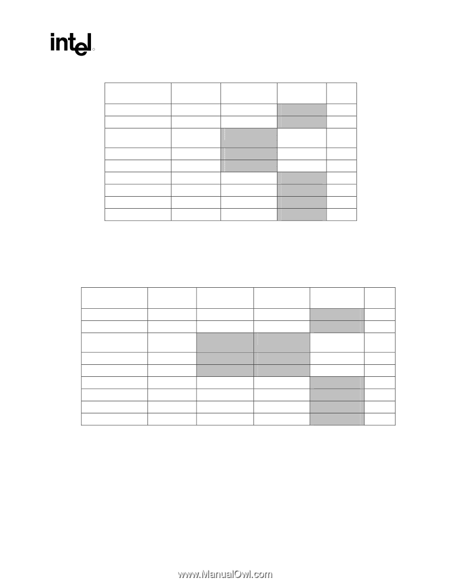
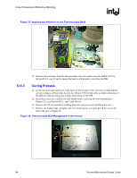
Table 8. ATX FSC Settings, Table 9. Balanced Technology Extended, BTX FSC Settings
 |
UPC - 683728178901
View all Intel 640 manuals
Add to My Manuals
Save this manual to your list of manuals |
Page 89 highlights
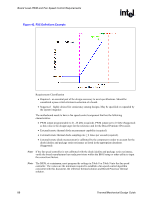
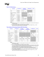
Board Level PWM and Fan Speed Control Requirements R Table 8. ATX FSC Settings Parameter Classification Processor Thermal Diode PWM Output Notes THIGH TLOW Minimum PWM Duty Cycle PWM Frequency Spin-up time TAVERAGING When TDIODE < TLOW All Fans ON Hysteresis Required Required Required Required Suggested Suggested Suggested Suggested Suggested TCONTROL 3 TCONTROL - 10 °C 3 20% 21-28 kHz 1 250 - ~500 ms 2 35 sec Minimum PWM% TCONTROL + 3 °C 2 °C NOTES: 1. A PWM output set to 25 kHz is the design target for the reference and for the Boxed Intel Processor and the reference design. 2. Use the lowest time available in this range for the device selected. 3. To ensure compliance with the thermal specification, thermal profile and usage of the TDIODE for fan speed control these setting should not be user configurable. Table 9. Balanced Technology Extended (BTX) FSC Settings Parameter Classificatio n Processor Thermal Diode System Ambient Diode PWM Output Notes THIGH Required TCONTROL 54 °C 3,5 TLOW Required TCONTROL - 7 °C 47 °C 3,5 Minimum PWM Duty Cycle Required PWM 1 (TMA) 20% PWM Frequency Required 21-28 kHz 1 Spin Up Time Suggested 250 - ~ 500 ms 2 TAVERAGING Suggested 4.0 sec 4.0 sec 3 When TDIODE < TLOW Suggested Minimum PWM% Minimum PWM% All Fans On Suggested TCONTROL + 3 °C 65 °C Hysteresis Suggested 2 °C 4 °C NOTES: 1. A PWM frequency of 25 kHz is the design target for the reference and for the Intel® Boxed Processor and the reference design. 2. Use the lowest time available in this range for the device selected 3. TAVERAGEING = represents the amount of delay time before responding to the temperature change, defined in fan speed control device (sometimes called ramp range control or spike smoothing). Please select the lowest setting available close to 4.0 seconds by the fan speed control device 4. The Fan Speed Controller, or Health Monitor Component, takes the result of the two fan speed ramps (processor and system) and drives the TMA fan to the highest resulting PWM duty cycle (%) 5. For BTX systems, a second thermal sensor is recommended to capture chassis ambient temperature (for more detail, see Appendix E). 6. To ensure compliance with the thermal specification, thermal profile and usage of the TDIODE for fan speed control these setting should not be user configurable. Thermal/Mechanical Design Guide 89
-
 1
1 -
2
-
3
-
4
-
5
-
6
-
7
-
8
-
9
-
10
-
11
-
12
-
13
-
14
-
15
-
16
-
17
-
18
-
19
-
20
-
21
-
22
-
23
-
24
-
25
-
26
-
27
-
28
-
29
-
30
-
31
-
32
-
33
-
34
-
35
-
36
-
37
-
38
-
39
-
40
-
41
-
42
-
43
-
44
-
45
-
46
-
47
-
48
-
49
-
50
-
51
-
52
-
53
-
54
-
55
-
56
-
57
-
58
-
59
-
60
-
61
-
62
-
63
-
64
-
65
-
66
-
67
-
68
-
69
-
70
-
71
-
72
-
73
-
74
-
75
-
76
-
77
-
78
-
79
-
80
-
81
-
82
-
83
-
 84
84 -
 85
85 -
 86
86 -
 87
87 -
 88
88 -
 89
89 -
 90
90 -
 91
91 -
 92
92 -
 93
93 -
 94
94 -
95
-
96
-
97
-
98
-
99
-
100
-
101
-
102
-
103
-
104
-
105
 |
 |