Intel 640 User Guide - Page 79
IHS Reference Groove on the 775-Land LGA Package, IHS Groove Orientation
 |
UPC - 683728178901
View all Intel 640 manuals
Add to My Manuals
Save this manual to your list of manuals |
Page 79 highlights
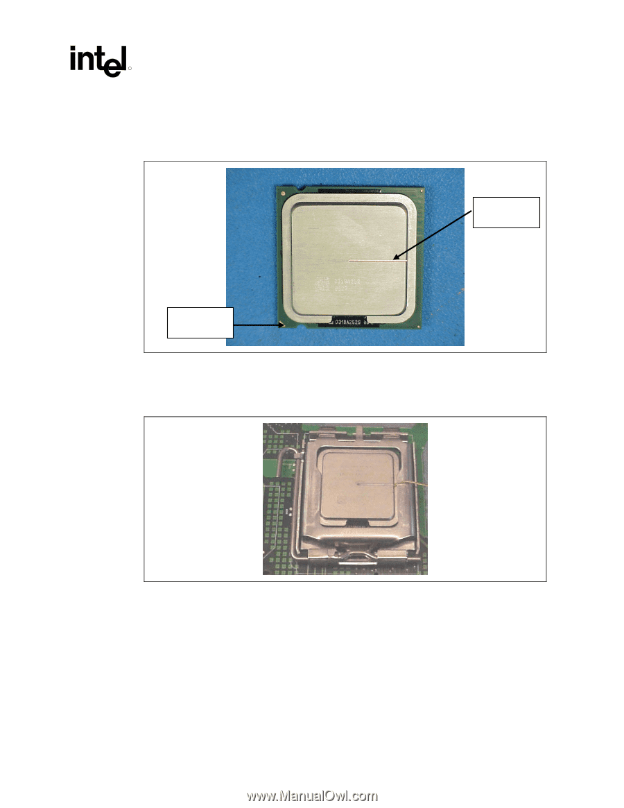
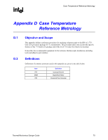
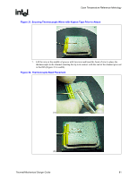
Case Temperature Reference Metrology R The orientation of the groove relative to the package pin 1 indicator (gold triangle in one corner of the package) is shown in Figure 28 for the 775-land LGA package IHS. Figure 28. IHS Reference Groove on the 775-Land LGA Package IHS Groove Pin1 indicator When the processor is installed in the LGA775 socket, the groove is perpendicular to the socket load lever, and on the opposite side of the lever, as shown in Figure 29. Figure 29. IHS Groove Orientation Relative to the LGA775 Socket Select a machine shop that is capable of complying with drawing specified tolerances. IHS channel geometry is critical for repeatable placement of the thermocouple bead, ensuring precise thermal measurements. The specified dimensions minimize the impact of the groove on the IHS under the socket load. A larger groove may cause the IHS to warp under the socket load such that it does not represent the performance of an ungrooved IHS on production packages. Inspect parts for compliance to specifications before accepting from machine shop. Thermal/Mechanical Design Guide 79
-
 1
1 -
2
-
3
-
4
-
5
-
6
-
7
-
8
-
9
-
10
-
11
-
12
-
13
-
14
-
15
-
16
-
17
-
18
-
19
-
20
-
21
-
22
-
23
-
24
-
25
-
26
-
27
-
28
-
29
-
30
-
31
-
32
-
33
-
34
-
35
-
36
-
37
-
38
-
39
-
40
-
41
-
42
-
43
-
44
-
45
-
46
-
47
-
48
-
49
-
50
-
51
-
52
-
53
-
54
-
55
-
56
-
57
-
58
-
59
-
60
-
61
-
62
-
63
-
64
-
65
-
66
-
67
-
68
-
69
-
70
-
71
-
72
-
73
-
 74
74 -
 75
75 -
 76
76 -
 77
77 -
 78
78 -
 79
79 -
 80
80 -
 81
81 -
 82
82 -
 83
83 -
 84
84 -
85
-
86
-
87
-
88
-
89
-
90
-
91
-
92
-
93
-
94
-
95
-
96
-
97
-
98
-
99
-
100
-
101
-
102
-
103
-
104
-
105
 |
 |