Intel 640 User Guide - Page 59
Combining Thermistor and Thermal Diode Control, Interaction of Thermal Profile and T
 |
UPC - 683728178901
View all Intel 640 manuals
Add to My Manuals
Save this manual to your list of manuals |
Page 59 highlights
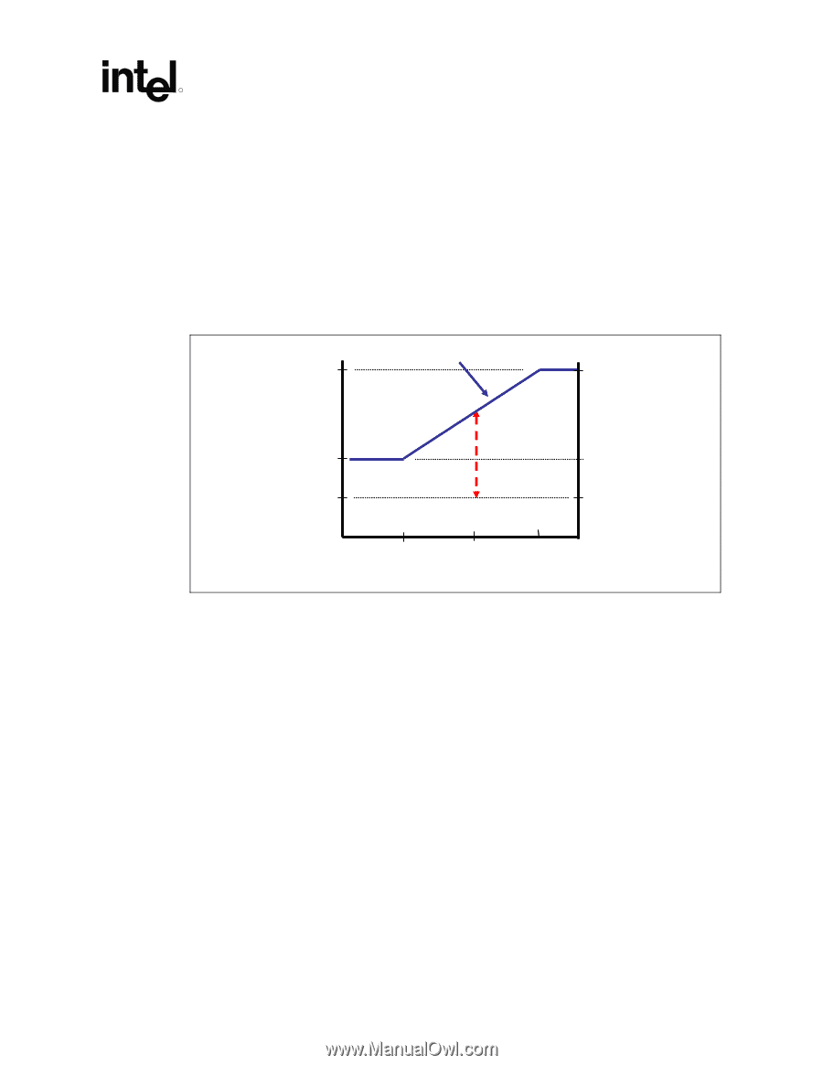
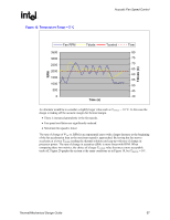
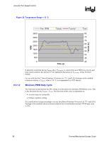
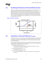
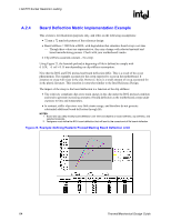
Acoustic Fan Speed Control R 6.4 Combining Thermistor and Thermal Diode Control There is no closed loop control between the FSC and the thermistor, but they work in tandem to provide the maximum fan speed reduction. As discussed in Section 6.2.2, the thermistor establishes the VSF curve. This curve will determine the maximum fan speed as a function of the ambient temperature and by design provides a ΨCA sufficient to meet the thermal profile. The FSC, by measuring the processor on-die thermal diode will command the fan to reduce speed below the VSF curve in response to processor workload. Conversely if the processor workload increases the FSC will command the fan via the PWM duty cycle to accelerate the fan up to the limit imposed by the VSF curve. Figure 21. Diode and Thermistor Full Speed Variable Speed Fan (VSF) Curve 100 % Fan Speed (RPM) Fan Speed (% PWM Duty Cycle) Min. Operating Fan Speed Operating Range with FSC Min % 6.5 30 34 38 Inlet Temperature (°C) Interaction of Thermal Profile and TCONTROL The Pentium 4 processor in the 775-land LGA packaged thermal specification is comprised of the two parameters, TCONTROL and the maximum case temperature defined by the Thermal Profile. The minimum requirement for thermal compliance is to ensure the thermal solution, by design, meets the thermal profile. If the system design will incorporate variable speed fan control, Intel requires monitoring the ondie thermal diode to implement acoustic fan speed control. The value of the on-die thermal diode temperature determines which specification must be met. • On-die Thermal Diode less than TCONTROL ⎯ When the thermal solution can maintain the thermal diode temperature to less than TCONTROL then the fan speed can be reduced. • On-die Thermal Diode equal to TCONTROL ⎯ The PWM duty cycle must be = 100% • On-die Thermal Diode greater than TCONTROL ⎯ The TC must be maintained at or below the Thermal Profile for the measured power dissipation. § Thermal/Mechanical Design Guide 59
-
 1
1 -
2
-
3
-
4
-
5
-
6
-
7
-
8
-
9
-
10
-
11
-
12
-
13
-
14
-
15
-
16
-
17
-
18
-
19
-
20
-
21
-
22
-
23
-
24
-
25
-
26
-
27
-
28
-
29
-
30
-
31
-
32
-
33
-
34
-
35
-
36
-
37
-
38
-
39
-
40
-
41
-
42
-
43
-
44
-
45
-
46
-
47
-
48
-
49
-
50
-
51
-
52
-
53
-
 54
54 -
 55
55 -
 56
56 -
 57
57 -
 58
58 -
 59
59 -
 60
60 -
 61
61 -
 62
62 -
 63
63 -
 64
64 -
65
-
66
-
67
-
68
-
69
-
70
-
71
-
72
-
73
-
74
-
75
-
76
-
77
-
78
-
79
-
80
-
81
-
82
-
83
-
84
-
85
-
86
-
87
-
88
-
89
-
90
-
91
-
92
-
93
-
94
-
95
-
96
-
97
-
98
-
99
-
100
-
101
-
102
-
103
-
104
-
105
 |
 |