Panasonic WJSX650 WJSX650 User Guide
Panasonic WJSX650 - SWITCHER Manual
 |
View all Panasonic WJSX650 manuals
Add to My Manuals
Save this manual to your list of manuals |
Panasonic WJSX650 manual content summary:
- Panasonic WJSX650 | WJSX650 User Guide - Page 1
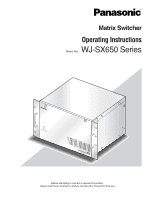
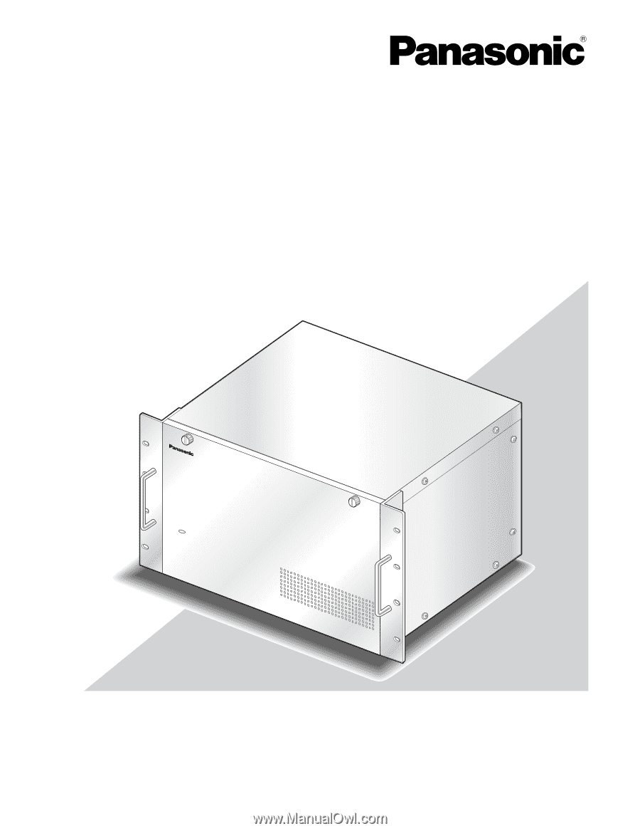
Matrix Switcher Operating Instructions Model Nos. WJ-SX650 Series OPERATE IF COOPLELRINAGTEFALNEDMWALILFLUNBLCITNIKONS 650 Matrix Switcher WJ-SX Before attempting to connect or operate this product, please read these instructions carefully and save this manual for future use. - Panasonic WJSX650 | WJSX650 User Guide - Page 2
). NO USER-SERVICEABLE PARTS INSIDE. REFER SERVICING TO QUALIFIED SERVICE PERSONNEL. SA limits for a Class A digital device, pursuant to Part 15 installed and used in accordance with the instruction manual installation of this product should be made by qualified service personnel or system installers - Panasonic WJSX650 | WJSX650 User Guide - Page 3
not block any ventilation openings. Install in accordance with the manufacturer's instructions. 8) Do not install near any heat sources such as unused for long periods of time. 14) Refer all servicing to qualified service personnel. Servicing is required when the apparatus has been damaged in any - Panasonic WJSX650 | WJSX650 User Guide - Page 4
PC 86 Glossary 87 Troubleshooting 89 I Matrix Switcher WJ-SX650 Series 89 I WJ-SX650 Series Administrator Console 93 I Power Cord, Connectors, and Power Plug 94 Specifications 95 I Matrix Switcher WJ-SX650 Series 95 I Card Cage WJ-SX650U 96 I Video Input Board WJ-PB65C32 96 I Video Output - Panasonic WJSX650 | WJSX650 User Guide - Page 5
BY THE LOCAL DEALER OF PANASONIC, FOR THE CASES INCLUDING USER; (4) INCONVENIENCE OR ANY LOSS ARISING WHEN IMAGES ARE NOT DISPLAYED, DUE TO ANY REASON OR CAUSE INCLUDING ANY FAILURE OR PROBLEM OF THE PRODUCT; (5) ANY PROBLEM, CONSEQUENTIAL INCONVENIENCE, OR LOSS OR DAMAGE, ARISING OUT OF THE SYSTEM - Panasonic WJSX650 | WJSX650 User Guide - Page 6
servicing other than that contained in the operating instructions user-serviceable parts inside. Contact qualified service installation. Do not touch components mounted on the boards directly by hand. Hold only both edges of the boards when installing system configuration, or when unexpected trouble - Panasonic WJSX650 | WJSX650 User Guide - Page 7
for installers and system administrators. This document uses the following terms for classification of devices. The (This ) unit: Matrix Switcher WJ-SX650 Video input board: Video Input Board WJ-PB65C32 Video output board: Video Output Board WJ-PB65M16 Recorder: Digital Disk Recorder WJ-HD300/WJ - Panasonic WJSX650 | WJSX650 User Guide - Page 8
, remote control of cameras, lenses, pan/tilt heads, and recorders (Digital Disk Recorder*) will be available. * Refer to p. 7 for details on model numbers. If you connect a personal computer (PC) to this product, control and system setup with WJ-SX650 Series Administrator Console will be available - Panasonic WJSX650 | WJSX650 User Guide - Page 9
Major Operating Controls and Their Functions I WJ-SX650 Matrix Switcher/WJ-SX650U Card Cage G Front View w OPERATE OPERATE LED WILL BLINK IF COOLING FAN MALFUNCTIONS q 650 Matrix Switcher WJ-SX q Operation Indicator (OPERATE) • This indicator is lighting while power is - Panasonic WJSX650 | WJSX650 User Guide - Page 10
the OUT X-3 board. i Expansion Slot For WJ-SX650, optional video input or output rear boards are installed. (Video Input Board WJ-PB65C32 or Video Output Board WJ-PB65M16) For WJ-SX650U, optional video input rear boards are installed. (Video Input Board WJ-PB65C32) o Video Output Board Rear Panels - Panasonic WJSX650 | WJSX650 User Guide - Page 11
29 28 27 26 25 24 23 22 21 20 19 18 17 16 15 14 13 12 11 10 9 8 7 6 5 4 3 2 1 CAMERA IN IN X-1 i !0 !1 IN A-3/IN B-3/IN C-3 board Note: These boards are originally installed into WJ-SX650 and WJ-SX650U, and not supplied to optional video input boards. (IN A-3 board is - Panasonic WJSX650 | WJSX650 User Guide - Page 12
Board WJ-PB65M16 Video output board is composed of a main board (installed into the front side) and rear boards (x 3)(installed into (DATA 1, 2) Each port connects to system controllers. u Data ports 3, 4 (DATA 3, 4) Each port connects to system controllers or recorders. i Rear Termination MODE - Panasonic WJSX650 | WJSX650 User Guide - Page 13
or the operating instructions of system controllers. q w Camera Information Camera number C001 to 999: Camera number R01 to 16: Recorder number Camera title Displays the registered camera title. Camera title setting is performed in "Camera" - "Camera Title" of WJ-SX650 Series Administrator Console - Panasonic WJSX650 | WJSX650 User Guide - Page 14
85 OPERATION (OTHER THAN TERMINAL MODE) or the operating instructions of system controllers. G WV-CU950/650 q w e rt y q Monitor Number Mon01 to 32: Monitor number w Camera Number Cam001 to 999: Camera number C-P0001 to 9999: Camera position number e Event HDR01 to 16: Recorder number Pre000 - Panasonic WJSX650 | WJSX650 User Guide - Page 15
number Note: This sign disappears when the camera is con- trolled. e Event The user. (Monitor busy) Note: You cannot control the selected monitor, camera, and recorder. When the CAMERA and BUSY indicators are lighting: A selected camera or recorder is controlled by a higher-priority user. (Camera - Panasonic WJSX650 | WJSX650 User Guide - Page 16
. • Use the following models for system expansion. Video input board: WJ-PB65C32 Video output board: WJ-PB65M16 Card Cage: WJ-SX650U • To connect Card Cage WJ-SX650U, Expansion Cable Kit WJ-CA65L07K (Option) or WJ-CA65L20K (Option) is required. • To record camera images by using a recorder, Dsub - Panasonic WJSX650 | WJSX650 User Guide - Page 17
the lower version to the higher one. (Refer to p. 41 or p. 54 for how to check the software version.) • Refer to the dealer for the version-up procedure. (Surely follow the instructions and notes.) I Switch Settings for Video Input Main Board With the switch settings of main boards, board numbers - Panasonic WJSX650 | WJSX650 User Guide - Page 18
I Switch Settings for Video Output Main Board When mounting an additional video input board, up to 32 monitors can be connected to the unit. SW1, SW2, SW3, SW4 1 2 SW4006 HOST FUNC Front view of video output main board TEST RESET MODE OFF 1 2 3 4 5 6 7 8 MODE switches To identify Video Output - Panasonic WJSX650 | WJSX650 User Guide - Page 19
I Mounting Video Input and Output Boards To use additional video input or output boards, mount these boards into the expansion slots of the unit after checking the board composition and performing switch settings (refer to pp. 16 to 18). The following is the figures describing recommended board - Panasonic WJSX650 | WJSX650 User Guide - Page 20
DATA 1 TMNTL1M/PNSLD5ATA TERM.ON TERM.OFF ON MODE MODE SIGNAL GND SIGNAL GND 3. Remove the front panel by loosening the screws. OPERATE 650 Matrix Switcher WJ-SX 4. Remove the blank panel from the front side. 2. Mount the rear boards into the expansion slot, and fix these boards with screws - Panasonic WJSX650 | WJSX650 User Guide - Page 21
I Installing the Main Unit Places to avoid • Places exposed to direct sunlight or Remove the rubber feet (4 psc.) on the bottom of the unit by loosening the screws. 650 Matrix Switcher WJ-SX 650 Matrix Switcher WJ-SX Important: • If the rack is subject to vibration, secure the rear of the unit to - Panasonic WJSX650 | WJSX650 User Guide - Page 22
Connections Important: Use only the recommended BNC connectors listed below. RECOMMENDED Tip dimensioins inside the BNC fl 1.32 mm - fl 1.37 mm Tip (inside) fl 0.13 mm - fl 0.69 mm BNC Video (coaxial) Cable Standards For U.S.A. For Europe For Japan MIL-C39012C or MIL-C39012/16F BS CECC 22120:1981 - Panasonic WJSX650 | WJSX650 User Guide - Page 23
WV-CU950/650 123456 78 WV-CU360C/CJ 123456 78 Terminal mode, Line termination: ON System controller SYSTEM CONTROLLER 123 456 789 0 A B SYSTEM CONTROLLER 123 456 789 0 A B MODE switches ON 123456 78 (#7: ON) (#8: OFF) Recorder SERIAL PC (WJ-SX650 Series Administrator Console) 23 - Panasonic WJSX650 | WJSX650 User Guide - Page 24
DATA Video output board DATA SERIAL DATA CAMERA IN Recorder Recorder DATA Recorder DATA Recorder System controller SYSTEM CONTROLLER 123 456 789 0 A B SYSTEM CONTROLLER 123 456 789 0 A B PC (WJ-SX650 Series Administrator Console) Recorder Recorder 24 Recorder Recorder MONITOR - Panasonic WJSX650 | WJSX650 User Guide - Page 25
board Video input board Video input board CAMERA IN MONITOR OUT Monitor 1 to 32 Card cage connection CAMERA IN Recorder DATA Recorder DATA Recorder DATA System controller SYSTEM CONTROLLER 123 456 789 0 A B SYSTEM CONTROLLER 123 456 789 0 A B PC (WJ-SX650 Series Administrator Console) - Panasonic WJSX650 | WJSX650 User Guide - Page 26
additional card cages. • Maximum unit connections: Matrix Switcher WJ-SX650 x 1, Card Cage WJ-SX650U x 3. • Video Output Board 1 and 11 10 9 8 7 6 5 4 3 2 1 CAMERA IN IN X-1 4 3 2 1 MODE RS485 (CAMERA) MODE MODE RS485 (CAMERA) MODE IN B-3 VIDEO OUT 4 VIDEO OUT 3 VIDEO OUT - Panasonic WJSX650 | WJSX650 User Guide - Page 27
4 switches (refer to p. 28) at video input rear boards. • Perform the RS-485 camera setting in RS485 CAMERA of SETUP MENU (refer to p. 53) or "System" - "VD2/DATA/Cable Comp." - "RS485 Camera" of WJ-SX650 Series Administrator Console. • 1 200 m {3 937 ft} is the total length limit of RS-485 cables - Panasonic WJSX650 | WJSX650 User Guide - Page 28
than 1 to 8 for individual cameras. (Refer to the operating instructions of camera for setting.) G Daisy Chain Connection Two or more cameras can be connected to one RS-485 (CAMERA) port. Up to 8 cameras are available. Example: RS-485 cameras are connected to the CAMERA IN 9 to 12 connectors Unit - Panasonic WJSX650 | WJSX650 User Guide - Page 29
1 Only OUT X-1 I PC Connection Refer to Serial (RS-232C) Connector Command Reference (PDF file on the supplied CD-ROM) for details on the connection and communication settings. PC (WJ-SX650 Series Administrator Console) Video Output Board 2 Video Output Board 1 DATA 4 DATA 3 HDR4/TMNL8 HDR3 - Panasonic WJSX650 | WJSX650 User Guide - Page 30
11 12 13 14 15 16 CAMERA IN connector of video input board 24 23 22 21 20 19 18 17 Note: To supply video input signals from recorders to video input boards, perform the settings surely in RECORDER of SETUP MENU (refer to p. 50) or "System" - "Recorder" of WJ-SX650 Series Administrator Console. 30 - Panasonic WJSX650 | WJSX650 User Guide - Page 31
directly to recorders. Note: Recorder settings are performed in RECORDER of SETUP MENU (refer to p. 50) or "System" - "Recorder" of WJ-SX650 Series Administrator Console. G Loop-thru Connection between Camera Input Connectors of Recorders and VIDEO OUT Ports of this Unit VIDEO OUT 1 to 4 ports are - Panasonic WJSX650 | WJSX650 User Guide - Page 32
VIDEO OUT ports of the unit to the camera input connectors of recorders if these camera input channels supply video output signals from recorders. devices. Setting changes are performed in "System" - "DATA Port" of WJ-SX650 Series Administrator Console or DATA PORT (refer to p. 52) of SETUP MENU. - Panasonic WJSX650 | WJSX650 User Guide - Page 33
following are abbreviations. • Unit Address S: Unit Address (System): • Unit Address C: Unit Address (Controller) Video 1 SIGNAL GND POWER AC IN Recorder Unit Address S: 2 Unit Address C: 2 LCN (Logical Camera Number): 17 to 32 Line termination: OFF 3 1 1 SERIAL ALARM 4 2 AUDIO IN AUDIO - Panasonic WJSX650 | WJSX650 User Guide - Page 34
controllers, perform the DATA port settings in DATA PORT of SETUP MENU (refer to p. 52) or "System" - "DATA Port" of WJ-SX650 Series Administrator Console. • Both of recorders and system controllers cannot be connected to the same DATA port. • 1 200 m {3 937 ft} is the total length limit of cables - Panasonic WJSX650 | WJSX650 User Guide - Page 35
system composition. When using 200 or more cameras in the PS·Data mode, apply WVCU950/650. Unit Address: 1 Line termination OFF Unit Address: 2 Line termination OFF Unit Address: 3 Line termination ON OPERATE OPERATE LED WILL BLINK IF COOLING FAN MALFUNCTIONS 650 Matrix Switcher WJ-SX OPERATE - Panasonic WJSX650 | WJSX650 User Guide - Page 36
of SETUP MENU (refer to p. 50) or "Alarm" - "Alarm Mode" - "Terminal Setup" of WJ-SX650 Series Administrator Console. • Perform the setting of each alarm event in "Alarm" - "Alarm Event" of WJ-SX650 Series Administrator Console. 19 18 17 16 15 14 13 12 11 10 9 8 7 6 5 4 3 2 1 I External Device - Panasonic WJSX650 | WJSX650 User Guide - Page 37
is also available.) For transmission, perform the serial command settings in "Communication" - "Serial Command" of WJ-SX650 Series Administrator Console. • To transmit SYSTEM STATUS records from the PC, refer to Serial (RS-232C) Connector Command Reference (PDF file on the supplied CD-ROM). 37 - Panasonic WJSX650 | WJSX650 User Guide - Page 38
unit is required. Setup is performed from WJ-SX650 Series Administrator Console installed on a PC. (Some settings are available from SETUP MENU of this unit.) The following is an example of setup procedure. Notes: • Setup may differ depending on system composition. (Settings of Step 1 and 4 in the - Panasonic WJSX650 | WJSX650 User Guide - Page 39
in WJ-SX650 Series Administrator Console> "System" - "Recorder" - "LCN Setting" Not available 7. Perform the camera title settings. CAM001 to 160: Enter desired camera titles. "Camera" - "Camera Title - Panasonic WJSX650 | WJSX650 User Guide - Page 40
WJ-SX650 Series Administrator Console This chapter explains about WJ-SX650 Series Administrator Console. Before controlling WJ-SX650 Series Administrator Console, installation on the PC is required. I System Requirements of a PC To install WJ-SX650 Series Administrator Console, the PC should meet - Panasonic WJSX650 | WJSX650 User Guide - Page 41
" - "Panasonic" - "WJSX650 Series" - "WJ-SX650 Series Administrator Console x.xx". (x.xx is the version number.) Then, run the program. WJ-SX650 Series Administrator Console will start up, and the login window will be displayed on the PC screen. Note: When you select "WJ-SX650 Series Administrator - Panasonic WJSX650 | WJSX650 User Guide - Page 42
for the setting items of "RS485" and "Unit number" in "System" - "VD2/DATA/Cable Comp." - "RS485 Camera". 8 Available parameters: Blank, 1 to 999 Note: Select the camera numbers that has been set in "System" - "Logical Camera Number". 9 [DATA1] TMNL1, PSD: Port type [DATA1] TMNL2: Port type - Panasonic WJSX650 | WJSX650 User Guide - Page 43
to 32: Page 27 Available parameters: 1 to 9999 28 Available parameters: 1 to 999 Note: You can select logical camera numbers that have been set in "System" - "Logical Camera Number". 29 Available parameters: Blank, 1 to 256 30 1 to 32: Tour sequence No. 31 Available parameters: 1 to 9999 - Panasonic WJSX650 | WJSX650 User Guide - Page 44
event. Available digits: 5 or less Available numerics System" - "RS485 Camera", the RS-485 settings are automatically canceled. 60 ON, OFF, AUTO, _: B/W setting 61 PATROL1(S) to PATROL4(S) , _: Scene [PATROL(S)] setting 62 ON: Perform OFF: Not perform Note: Depending on the specifications - Panasonic WJSX650 | WJSX650 User Guide - Page 45
in SETUP MENU. I Factory Default Settings of WJSX650 Series Administrator Console G System "Recorder" Recorder Output: External Monitor Recorder 1 last Sunday in October G Camera "Camera Title" CAM 1 • • 256 Camera Title 1 • • 256 Custom Chars: A to Z, a to f "Camera Position" CAM-P 1 to - Panasonic WJSX650 | WJSX650 User Guide - Page 46
OFF* "Alarm Event" Terminal Alarm 1 to 256: SPOT, LCN 1 to 256, Monitor 1 Camera Alarm 1 to 256: No settings Recorder Alarm 1 to 256: No settings Serial Alarm 1 to User ID: 650 HDR Operation Using the Web Browser: Priority: 1 "Level Table" Item System Setup OSD Control Alarm History Display System - Panasonic WJSX650 | WJSX650 User Guide - Page 47
are enabled. (Checked) (User ID: 650) Auto Logout: All the ports are unabled. (Not Checked) "Key Assignment" (Available for WV-CU950/650) DATA 1 to 8 A B TOP Function Iris Reset Auto Focus Auto Focus G Communication "Serial Command" Alarm Notification: OFF System Status - Panasonic WJSX650 | WJSX650 User Guide - Page 48
monitor. G WV-CU950/650 1. Select a desired monitor. (Refer to p. 57 Monitor Selection.) 2. Press the MENU button repeatedly until "System Setup" appears on the MENU is opened, the top menu is displayed on the monitor. WJ-SX650 SETUP MENU 100 TIME&DATEO 300 ALARMO 400 RECORDERO 500 SYSTEMO 800 - Panasonic WJSX650 | WJSX650 User Guide - Page 49
"Display" of WJ-SX650 Series Administrator Console. I ALARM You will perform the settings of alarms (terminal alarms, camera alarms, recorder alarms an alarm is automatically reset. If you select OFF, you will reset the alarm manually. (The factory default is 30 sec.) OFF/1, 2... to 10 sec/20 sec/ - Panasonic WJSX650 | WJSX650 User Guide - Page 50
, the following menu is displayed. Note: Before the settings, check the system composition and refer to p. 30 Recorder Connection. 400 RECORDER 1 of 2 ON 15 HDR4 OFF 16 HDR4 0FF DATA=DATA(TMNL/PSD/HDR) CAM=CAMERA IN • RECORDER OUTPUT Select the video input board or external monitor to supply - Panasonic WJSX650 | WJSX650 User Guide - Page 51
parameters surely for these camera input channels, even though these channels accept video input signals from recorders. Without LCN settings, recorder selection is unavailable. The channel settings are performed in "System" - "Recorder" of WJ-SX650 Series Administrator Console. • Be sure to connect - Panasonic WJSX650 | WJSX650 User Guide - Page 52
You will perform the settings for VD2, camera control signal (DATA), and cable compensation. • RS485 CAMERA RS485 CAMERA menu is displayed. You will set the in the terminal mode. PSD: Select this when using the DATA port for system con- troller in the PS·Data mode. HDR1 to 4: Select this when - Panasonic WJSX650 | WJSX650 User Guide - Page 53
29 8 1 of 2 CAM RS485 233 30 234 30 235 30 236 30 237 238 239 240 UNIT 1 2 3 4 COMMUNICATION STATUS 19200/8/ NONE/1 CAM=CAMERA IN RS485=RS485(CAMERA) 540 RS485 CAMERA INPUT BOARD=8 CAM RS485 UNIT 241 31 1 242 32 1 243 244 245 246 247 248 2 of 2 CAM RS485 249 250 251 252 253 - Panasonic WJSX650 | WJSX650 User Guide - Page 54
I INFORMATION You can check whether the connected video input or output boards are working properly. When you select INFORMATION on the top menu, the following menu is displayed. 800 INFORMATION OUTPUT BOARD1 V1.01 OUTPUT BOARD2 V1.01 INPUT BOARD1 ∗ INPUT BOARD2 ∗ INPUT BOARD3 ∗ INPUT BOARD4 ∗ INPUT - Panasonic WJSX650 | WJSX650 User Guide - Page 55
WJ-SX650 Series Administrator Console. The factory default of operator information is as follows. Operator No. User ID 1 650 2 1 3 100 4 101 5 102 6 103 Password 650 Level 1 12345 1 100 2 101 3 102 4 103 5 Priority 1 1 5 10 30 50 Camera Access View & Operate (All cameras - Panasonic WJSX650 | WJSX650 User Guide - Page 56
auto login and auto logout settings is performed in "Controller" - "Auto Login/Logout" of WJ-SX650 Series Administrator Console. • Auto login and auto logout are set for each DATA port. Operators logging into the system from the same DATA port have the common setting. • When both auto login and auto - Panasonic WJSX650 | WJSX650 User Guide - Page 57
on the selected monitor. I Monitor Lock When you log out of the system or select another monitor, this function can prevent operators with lower priority from gaining control of the selected monitor and camera(s). G WV-CU950/650 1. Press the MON LOCK button. The selected monitor will be locked - Panasonic WJSX650 | WJSX650 User Guide - Page 58
will appear on the LCD (or LED display). 3. Control the selected camera. I Camera Selection Recall Every time you select a camera or camera position, a system controller memorizes up to 10 steps of camera selection. You can recall these steps in order or reverse - Panasonic WJSX650 | WJSX650 User Guide - Page 59
will be moved to the home positions. • All auxiliaries OFF: AUX 1 and 2 outputs of cameras will become OFF. Note: This operation is not available for cameras restricted by the operator's setting. G WV-CU950/650 1. Press the MENU button repeatedly until "All CAM Control" appears on the LCD. 2. Press - Panasonic WJSX650 | WJSX650 User Guide - Page 60
Camera 3 will be activated, and recorded image of Camera 3 will be played back. *1 WV-CU950/650 *2 WV-CU360C/CJ WV-CU950/650 WV-CU360C/360CJ I Manual Recording G WV-CU950/650 a recorded image to play back. Refer to the operating instructions of recorder for operating procedures. G WV-CU360C/CJ 1. - Panasonic WJSX650 | WJSX650 User Guide - Page 61
WJ-HD300 Series finish recorder control, select a camera. The monitor display will become open SETUP MENU of Recorder 16. G WV-CU950/650 1. Enter the desired recorder number by pressing the numeric be selected. 3. Press the MENU button repeatedly until "System Setup" appears on the LCD. 4. Press the - Panasonic WJSX650 | WJSX650 User Guide - Page 62
according to the setting. • Up to 32 tour sequences can be registered. • Up to 64 steps can be set for a tour sequence. G Group Sequence Camera images are displayed on two or more monitors, and they are sequentially switched according to the setting. • Up to 8 group sequences can be registered - Panasonic WJSX650 | WJSX650 User Guide - Page 63
is performed in "Sequence" of WJ-SX650 Series Administrator Console. The following settings are available for each sequence step. Setting item LCN (Logical Camera Number) Preset AUX1/2 Dwell Parameter 1 to 999 1 to 256 ON, OFF, - 1 to 30 sec Remarks Camera position numbers are also available for - Panasonic WJSX650 | WJSX650 User Guide - Page 64
will appear on the LCD. I Group Sequence/Preset G WV-CU950/650 1. Select a monitor assigned for desired group sequence/preset. (Refer to in Step 2, group preset will be activated. The system status will be the same as that after camera selection. • Group sequence/preset will not be activated - Panasonic WJSX650 | WJSX650 User Guide - Page 65
. I Sequence Stop When a tour or group sequence is stopped, the camera at the stopped step will be selected. When a group sequence is stopped on a monitor, all sequences will be simultaneously stopped on other monitors. G WV-CU950/650 Press the SEQ STOP button while holding down the SHIFT button - Panasonic WJSX650 | WJSX650 User Guide - Page 66
setting is performed in "Communication" - "Serial Command" of WJ-SX650 Series Administrator Console. Camera 100 This unit Alarm Output 50 Preset Position 1 (Zooming in No.1 (Entrance)) Terminal Alarm 256 650 Matrix Switcher WJ-SX Monitor 5 No.1 (Entrance) Alarm input signal from a sensor - Panasonic WJSX650 | WJSX650 User Guide - Page 67
on a monitor) are available. (Regardless of alarm modes, alarms occur to all the associated cameras.) The alarm mode setting is performed in "Alarm" - "Alarm Mode" of WJ-SX650 Series Administrator Console or the ALARM menu of SETUP MENU. • Sequence mode Alarm pictures are sequentially displayed on - Panasonic WJSX650 | WJSX650 User Guide - Page 68
panning/tilting of cameras, or move cameras to preset positions, etc. I Alarm Picture Change When two or more alarms are occurring, you can change alarm pictures displayed on the monitor in order or reverse order. G WV-CU950/650 the system will Mode" of WJSX650 Series Administrator Console or the - Panasonic WJSX650 | WJSX650 User Guide - Page 69
WJ-SX650 Series Administrator Console. • To reset the alarms occurred to recorders, perform alarm all reset. Alarm all reset is available even while no alarms are occurring. I Return to Alarm Mode Status You can recover from the ACK status to the alarm mode status. G WV-CU950/650 C-CAMERA R- - Panasonic WJSX650 | WJSX650 User Guide - Page 70
001 to Camera 999 was activated for spot mode. T01 to 32: Tour Sequence 1 to 32 was activated. G01 to 32: Group sequence (or Group preset) 1 to 32 was activated. Notes: • User ID and Controller information is displayed for an alarm reset or suspended by an operator. (They are not displayed for - Panasonic WJSX650 | WJSX650 User Guide - Page 71
activate daily or weekly. The camera event setting is performed in "Schedule" - "Camera Event" of WJ-SX650 Series Administrator Console. The following camera events are available. (Refer to the operating instructions of cameras for details.) G Auto Track • ALARM IN (Camera) - Use Select this setting - Panasonic WJSX650 | WJSX650 User Guide - Page 72
, perform the setting in the setup menu of camera. (Refer to the operating instructions of camera for setting.) G BW and Scene [PATROL(S)] • BW ON: The camera is changed to the black and white mode. OFF: The camera is changed to the color mode. AUTO: The camera is changed to the black and white mode - Panasonic WJSX650 | WJSX650 User Guide - Page 73
be given restrict levels for each operation and function according to the user level settings. I Lists of Operations and Functions • [q] means status. Not available (No LCD on this system controller) WV-CU950/650: Exit SETUP MENU before this operation. ( instructions of system controller. 73 - Panasonic WJSX650 | WJSX650 User Guide - Page 74
and WV-CU360C/CJ Function Login q Enters the user ID. w Enters the password. Logout WV-CU950/650 Enter the number. (Numeric buttons) → [CAM Numeric buttons) → [MON (ESC)] [SHIFT] + [MON LOCK] Camera Selection • Selects the next camera. • Selects the previous cam- era. Enter the number. (Numeric - Panasonic WJSX650 | WJSX650 User Guide - Page 75
SETUP MENU. WV-CU950/650 Open "System Setup" main menu. → [F1] WV-CU360C/CJ [SHIFT] + [SETUP] [F2] [SHIFT] + [SETUP] On-screen display (OSD) ON/OFF • All the information Open "OSD On/Off" main menu. → [SHIFT] + [F1] [OSD] + [ALL] • Time and date information [F1] • Camera information [F2 - Panasonic WJSX650 | WJSX650 User Guide - Page 76
Status Display. Alarm History Display WV-CU950/650 Open "System Status" main menu. → [F1] WV-CU360C/CJ [OSD] + [SYS S] [F2] [OSD] + [SYS S] not available on monitors in the alarm mode or during recorder selection. WV-CU950/650, WVCU360C/CJ: An alarm whose Display Mode setting is OFF will not be - Panasonic WJSX650 | WJSX650 User Guide - Page 77
up while this button is held down. WV-CU950/650, WVCU360C/CJ: Lens iris will keep closing down while this button is held down. WV-CU950/650: You can assign another function to this button. The setting is performed in "Controller" - "Key Assignment" of WJ-SX650 Series Administrator Console. 77 - Panasonic WJSX650 | WJSX650 User Guide - Page 78
to these buttons . The setting is performed in "Controller" - "Key Assignment" of WJ-SX650 Series Administrator Console. Zoom control • Widen the scene. Zoom wheel controller to the [ZOOM WIDE] left WV-CU950/650: Lens zooming level will keep going down while zoom wheel controller is being moved - Panasonic WJSX650 | WJSX650 User Guide - Page 79
LED display. )→ [3] • Sort [F2] [2] • Auto pan [F3] [1] • Patrol [F4] Refer to p. 78 Patrol 650: If the camera has only one AUTO mode, press this button. WV-CU950/650, WVCU360C/CJ: • Mode setting is determined by the DIP switch settings of auxiliary device (receiver, etc.). (Cameras support - Panasonic WJSX650 | WJSX650 User Guide - Page 80
CU950/650, WV-CU360C/CJ: Refer to the operating instructions of cameras for camera function numbers. Recorder control Function Recorder Setup WV-CU950/650 Open "System Setup /650: You cannot select COPY 1 for WJ-HD300 Series. WV-CU950/650: You cannot select COPY 2 for WJ-HD300 Series. WV-CU950/650: - Panasonic WJSX650 | WJSX650 User Guide - Page 81
the recorder. Note: To stop the sequence, perform sequence stop. Refer to p. 74. WV-CU950/650: When a camera is selected, manual recording is started for the recorder connected to the camera. WV-CU950/650, WVCU360C/CJ: • Every pressing this button can change search list display. • Refer to p. 73 - Panasonic WJSX650 | WJSX650 User Guide - Page 82
/CJ: During playback, the recorded images of cameras are interchangeably displayed by: • Camera selection • Selects the next/previous camera. WV-CU950/650: • When a camera is selected, the latest recorded image of camera is played back. • For WJ-HD300 Series, this operation is available only during - Panasonic WJSX650 | WJSX650 User Guide - Page 83
- - Not available • Camera selection Refer to p. 74 Camera selec- - tion. • Selects the next camera. Refer to p. 74 Selects the next - camera. • Selects the previous cam Playback is started when you mark the end point. WV-CU950/650: • Hold down this button until the operation end. • These - Panasonic WJSX650 | WJSX650 User Guide - Page 84
I Menu Flow (WV-CU950/650) If you press the MENU button without selecting a recorder Keep pressing the SHIFT button. Keep pressing the SHIFT button. : SHIFT + MENU buttons : MENU button If - Panasonic WJSX650 | WJSX650 User Guide - Page 85
Operator" - "Operator" of WJ-SX650 Series Administrator Console. • Logout Auto logout is not available. Log out from the system manually. • Camera selection When using WV-CU360C/CJ, you cannot select Camera 200 or greater. • Camera position When using WV-CU950/650, camera positions registered in the - Panasonic WJSX650 | WJSX650 User Guide - Page 86
changes are performed in "System" - "DATA Port" of WJ-SX650 Series Administrator Console or DATA PORT (refer to p. 52) of SETUP MENU. Unit Address: 1 Unit Address: 2 Unit Address: 3 OPERATE OPERATE LED WILL BLINK IF COOLING FAN MALFUNCTIONS 650 Matrix Switcher WJ-SX OPERATE OPERATE LED WILL - Panasonic WJSX650 | WJSX650 User Guide - Page 87
in "System" - "Logical Camera Number" of WJ-SX650 Series Administrator Console. Recorder number: Unit Address (System) instructions of cameras supporting this function. Patrol: Camera's function to learn and reproduce camera operations and picture quality. (Refer to pp. 71 and 78.) Cleaning (Camera - Panasonic WJSX650 | WJSX650 User Guide - Page 88
of tour sequence or group sequence in export files (csv format). This function is available when using WJ-SX650 Series Administrator Console. Export is performed separately for each sequence program. Import: Function to read export files (csv format) into WJSX650 Series Administrator Console. 88 - Panasonic WJSX650 | WJSX650 User Guide - Page 89
Troubleshooting Check the following before requesting repair. If a trouble cannot be corrected even after checking and trying remedy, contact your dealer. I Matrix Switcher WJ-SX650 Series Problem Check item and remedy Reference Power is not turned on. • Check if the power plug is properly - Panasonic WJSX650 | WJSX650 User Guide - Page 90
powered on or a camera is connected, black bars may be seen on the monitor for several seconds with images not supporting VD2 (images from camera input channel accepting video input signals from the recorder. Check the setting in 51 "System" - "Recorder" of WJ-SX650 Series Administrator Console - Panasonic WJSX650 | WJSX650 User Guide - Page 91
the selected system controller becomes unavailable to the operating instructions of recorder for WJ-HD300 Series: Ver. 1.61 or later 30 WJ-HD300A Series: Ver. 3.10 or later • Check if the sequence setting contains LCN's or camera positions not registered. (When the setting contains camera - Panasonic WJSX650 | WJSX650 User Guide - Page 92
Problem Auto tracking ended before the end time of camera event setting. Alarm event does not occur. The image of camera associated with the alarm event was not recorded. The status before the alarm occurrence is not recovered, even though the alarm event is reset. Alarm - Panasonic WJSX650 | WJSX650 User Guide - Page 93
WJ-SX650 Series Administrator Console Problem Check item and remedy Reference "!" mark is displayed in the LCN entry field. • Check if the camera number not registered is set for the cam- era position, tour sequence, group sequence, timer event, alarm event, recorder, or camera in "System" - - Panasonic WJSX650 | WJSX650 User Guide - Page 94
, Connectors, and Power Plug Check the power cord, connectors, and power plug regularly. Problem Check item and remedy The power cord insulation is damaged. Reference The power cord, plug . Unplug the power plug from the AC outlet immediately, and refer to qualified service per- - sonnel. 94 - Panasonic WJSX650 | WJSX650 User Guide - Page 95
Specifications I Matrix Switcher WJ-SX650 Series Power Source: 120 V AC, 60 Hz Power Consumption: 60 W Ambient Operating Temperature: -10 °C to +50 °C {14 °F to 122 °F}*1 Ambient Operating Humidity: Less than 90 % Video Input Board: x 1 Camera Input (CAMERA (TMNL)/Digital disk recorder - Panasonic WJSX650 | WJSX650 User Guide - Page 96
WJ-SX650U Power Source: Power Consumption: Ambient Operating Temperature: Ambient Operating Humidity: Expansion slot: RS-485 (Camera Data Mode (PS·DATA) selectable*8) Terminal Mode (TMNL) Terminal Mode (TMNL)/Digital disk recorder (HDR) selectable 6-conductor modular jack x 4 (With termination - Panasonic WJSX650 | WJSX650 User Guide - Page 97
files are included on the CD-ROM. • WJ-SX650 Series Administrator Console (Application) • Operating Instructions (PDF file: French version) • Serial (RS-232C) Connector Command Reference (PDF file) Warranty Card 1 pc. The following part is used during installation procedures. Power Cord 1 pc. 97 - Panasonic WJSX650 | WJSX650 User Guide - Page 98
Solutions Company, Unit Company of Panasonic Corporation of North America Security Systems www.panasonic.com/security For customer support, call 1.877.733.3689 Executive Office: Three Panasonic Way 2H-2, Secaucus, New Jersey 07094 Zone Office Eastern: Three Panasonic Way, Secaucus, New Jersey 07094
-
 1
1 -
 2
2 -
 3
3 -
 4
4 -
 5
5 -
 6
6 -
 7
7 -
8
-
9
-
10
-
11
-
12
-
13
-
14
-
15
-
16
-
17
-
18
-
19
-
20
-
21
-
22
-
23
-
24
-
25
-
26
-
27
-
28
-
29
-
30
-
31
-
32
-
33
-
34
-
35
-
36
-
37
-
38
-
39
-
40
-
41
-
42
-
43
-
44
-
45
-
46
-
47
-
48
-
49
-
50
-
51
-
52
-
53
-
54
-
55
-
56
-
57
-
58
-
59
-
60
-
61
-
62
-
63
-
64
-
65
-
66
-
67
-
68
-
69
-
70
-
71
-
72
-
73
-
74
-
75
-
76
-
77
-
78
-
79
-
80
-
81
-
82
-
83
-
84
-
85
-
86
-
87
-
88
-
89
-
90
-
91
-
92
-
93
-
94
-
95
-
96
-
97
-
98
 |
 |
Before attempting to connect or operate this product,
please read these instructions carefully and save this manual for future use.
Matrix Switcher WJ-SX
650
OPERATE
OPERATE LED WILL BLINK
IF COLLING FAN MALFUNCTIONS
Matrix Switcher
Operating Instructions
Model Nos.
WJ-SX650 Series