Panasonic WJSX650 WJSX650 User Guide - Page 51
CAM Camera input channel No.: Video Input board 1 to 8
 |
View all Panasonic WJSX650 manuals
Add to My Manuals
Save this manual to your list of manuals |
Page 51 highlights
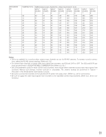
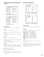
RECORDER No. 1 2 3 4 5 6 7 8 9 10 11 12 13 14 15 16 CAMERA IN No. CAM (Camera input channel No.: Video Input board 1 to 8) INPUT BOARD 1 INPUT BOARD 2 INPUT BOARD 3 INPUT BOARD 4 INPUT BOARD 5 INPUT BOARD 6 32 32 64 96 128 160 192 31 31 63 95 127 159 191 30 30 62 94 126 158 190 29 29 61 93 125 157 189 28 28 60 92 124 156 188 27 27 59 91 123 155 187 26 26 58 90 122 154 186 25 25 57 89 121 153 185 24 24 56 88 120 152 184 23 23 55 87 119 151 183 22 22 54 86 118 150 182 21 21 53 85 117 149 181 20 20 52 84 116 148 180 19 19 51 83 115 147 179 18 18 50 82 114 146 178 17 17 49 81 113 145 177 INPUT BOARD 7 224 223 222 221 220 219 218 217 216 215 214 213 212 211 210 209 INPUT BOARD 8 256 255 254 253 252 251 250 249 248 247 246 245 244 243 242 241 Notes: • ON is not available for recorders when camera input channels are set for RS-485 cameras. To activate recorder connections, delete the RS-485 camera settings. (Refer to p. 53.) • For camera input channels to supply video input signal from recorders, set VD2 and DATA to OFF. The VD2 and DATA settings are performed in VD2/DATA/CABLE COMPENSATION. (Refer to p. 53.) • Set LCN parameters surely for these camera input channels, even though these channels accept video input signals from recorders. Without LCN settings, recorder selection is unavailable. The channel settings are performed in "System" - "Recorder" of WJ-SX650 Series Administrator Console. • Be sure to connect the recorders to the specified DATA ports in the daisy chain. (Refer to p. 32 for connections.) • Be sure to supply the video input signals from recorders to the specified camera input channels. (Refer to p. 30 for connections.) 51
-
 1
1 -
2
-
3
-
4
-
5
-
6
-
7
-
8
-
9
-
10
-
11
-
12
-
13
-
14
-
15
-
16
-
17
-
18
-
19
-
20
-
21
-
22
-
23
-
24
-
25
-
26
-
27
-
28
-
29
-
30
-
31
-
32
-
33
-
34
-
35
-
36
-
37
-
38
-
39
-
40
-
41
-
42
-
43
-
44
-
45
-
 46
46 -
 47
47 -
 48
48 -
 49
49 -
 50
50 -
 51
51 -
 52
52 -
 53
53 -
 54
54 -
 55
55 -
 56
56 -
57
-
58
-
59
-
60
-
61
-
62
-
63
-
64
-
65
-
66
-
67
-
68
-
69
-
70
-
71
-
72
-
73
-
74
-
75
-
76
-
77
-
78
-
79
-
80
-
81
-
82
-
83
-
84
-
85
-
86
-
87
-
88
-
89
-
90
-
91
-
92
-
93
-
94
-
95
-
96
-
97
-
98
 |
 |