Panasonic WJSX650 WJSX650 User Guide - Page 27
Camera Connections, Rs-485 Camera Connections
 |
View all Panasonic WJSX650 manuals
Add to My Manuals
Save this manual to your list of manuals |
Page 27 highlights
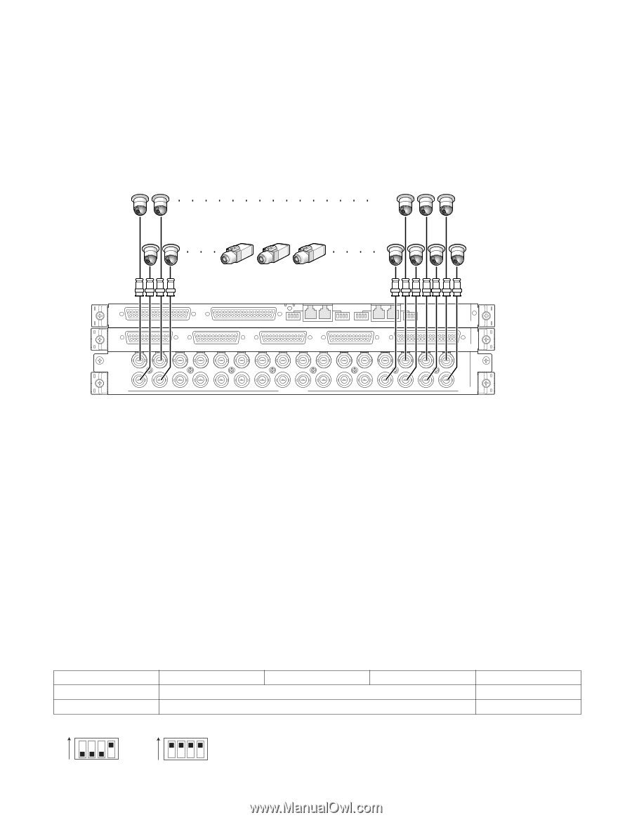
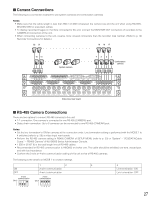
I Camera Connections The following is a connection example to use system cameras and combination cameras. Notes: • Make sure that the cable length is less than 900 m {3 000 ft} between the camera site and the unit when using RG-59/U, BELDEN 9259 or equivalent cables. • To display recorded images on monitors connected to this unit, connect the MONITOR OUT connectors of recorders to the CAMERA IN connectors of the unit. • When connecting cameras to the unit, reserve more unused connectors than the recorder total number. (Refer to p. 30 Recorder Connections for details.) 32 31 19 18 17 16 15 System camera 43 2 1 Combination camera 4 3 2 1 EXTENSION 3 IN EXTENSION 2 IN MODE RS485 (CAMERA) MODE MODE RS485 (CAMERA) MODE IN C-3 VIDEO OUT 4 VIDEO OUT 3 VIDEO OUT 2 VIDEO OUT 1 ALARM IN IN X-2 32 31 30 29 28 27 26 25 24 23 22 21 20 19 18 17 16 15 14 13 12 11 10 9 8 7 6 5 4 3 2 1 CAMERA IN IN X-1 Video input rear board I RS-485 Camera Connections There are two options to connect RS-485 cameras to this unit. • 1:1 connection: One camera is connected to one RS-485 (CAMERA) port. • Daisy chain connection: Up to 8 cameras can be connected to one RS-485 (CAMERA) port. Notes: • Set the line termination to ON for cameras at the connection ends. Line termination setting is performed with the MODE 1 to 4 switches (refer to p. 28) at video input rear boards. • Perform the RS-485 camera setting in RS485 CAMERA of SETUP MENU (refer to p. 53) or "System" - "VD2/DATA/Cable Comp." - "RS485 Camera" of WJ-SX650 Series Administrator Console. • 1 200 m {3 937 ft} is the total length limit of RS-485 cables. • Recommended for RS-485 communication is AWG#22 or thicker one. The cable should be shielded, two-wire, twisted pair, and with low impedance. • Conform the 2-wire or 4-wire communication setting of this unit to that of RS-485 cameras. The following is the details on MODE 1 to 4 switch settings. 1 2 3 ON 2-wire communication OFF 4-wire communication 4-wire communication ON 2-wire communication ON 4 Line termination: ON Line termination: OFF 1234 1234 27
-
 1
1 -
2
-
3
-
4
-
5
-
6
-
7
-
8
-
9
-
10
-
11
-
12
-
13
-
14
-
15
-
16
-
17
-
18
-
19
-
20
-
21
-
 22
22 -
 23
23 -
 24
24 -
 25
25 -
 26
26 -
 27
27 -
 28
28 -
 29
29 -
 30
30 -
 31
31 -
 32
32 -
33
-
34
-
35
-
36
-
37
-
38
-
39
-
40
-
41
-
42
-
43
-
44
-
45
-
46
-
47
-
48
-
49
-
50
-
51
-
52
-
53
-
54
-
55
-
56
-
57
-
58
-
59
-
60
-
61
-
62
-
63
-
64
-
65
-
66
-
67
-
68
-
69
-
70
-
71
-
72
-
73
-
74
-
75
-
76
-
77
-
78
-
79
-
80
-
81
-
82
-
83
-
84
-
85
-
86
-
87
-
88
-
89
-
90
-
91
-
92
-
93
-
94
-
95
-
96
-
97
-
98
 |
 |