Panasonic WJSX650 WJSX650 User Guide - Page 95
Specifications, Matrix Switcher Wj-sx650 Series
 |
View all Panasonic WJSX650 manuals
Add to My Manuals
Save this manual to your list of manuals |
Page 95 highlights
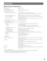
Specifications I Matrix Switcher WJ-SX650 Series Power Source: 120 V AC, 60 Hz Power Consumption: 60 W Ambient Operating Temperature: -10 °C to +50 °C {14 °F to 122 °F}*1 Ambient Operating Humidity: Less than 90 % Video Input Board: x 1 Camera Input (CAMERA IN 1 to 32): 1 V [P-P]/75 Ω (BNC x 32), composite video signal 0.5 V [P-P]/75 Ω data signal and 2.5 V [P-P]/75 Ω vertical timing pulse multi- plexed Video Output (VIDEO OUT 1 to 4): 1 V [P-P]/75 Ω (25-pin D-sub connector x 4)*2, active loop-thru output Alarm Input (ALARM IN): N.O. (Normally Open contact) or N.C. (Normally Close contact) selectable x 32 (37-pin D-sub connector) RS-485 (Camera) Port: 6-conductor modular jack x 4 (2-wire or 4-wire communication, with termination switches (MODE 1 to 4)) Extension Port (EXTENSION IN 2, 3): 37-pin D-sub connector x 2 Video Output Board: x 1 Monitor Output (MONITOR OUT 1 to 16): 1 V [P-P]/75 Ω (BNC x 16) Data Port (DATA 1 to 4) DATA 1: Terminal Mode (TMNL) (PS·Data Mode (PS·DATA) selectable*3) DATA 2: Terminal Mode (TMNL) DATA 3, 4: Terminal Mode (TMNL)/Digital disk recorder (HDR) selectable 6-conductor modular jack x 4 (With termination switches (MODE 1 to 4)) Alarm Output (ALARM OUT 1, 2) Alarm Output: Open collector output x 32, Max. 24 V DC, 100 mA Alarm Recover Output: Non-voltage make contact input x 16 Time Adjust Input*3: Non-voltage make contact input x 1 Time Adjust Output*3: Open collector output x 1, Max. 24 V DC, 100 mA Extension Port (EXTENSION 1 IN, OUT)*3: 6-conductor modular jack x 2 (With a termination switch (TERM: ON, OFF)) VS Input*3: 1 V [P-P]/75 Ω (VS IN) VS Output*3: (VS OUT (THRU)): VS loop-thru output (VS OUT): 1 V [P-P]/75 Ω (VS) Serial Port*3: 9-pin D-sub connector x 2 Expansion slot: x 1 RS-485 (Camera) Port*4: 6-conductor modular jack x 4 (2-wire or 4-wire communication, with termination switches (MODE 1 to 4)) Functions: Monitor control (Camera selection, tour sequence, group sequence, group pre- set, OSD display) Camera/Receiver control (Coaxial/RS-485 communication) Recorder control Alarm control (Alarm event, Alarm ACK, Alarm reset, Alarm suspension, Alarm History Display) Timer event, Camera event Dimensions: 420 mm (W) X 265 mm (H) X 372 mm (D) {16-9/16" (W) X 10-2/5" (H) X 14-3/5" (D)} (excluding rubber feet and projections) Weight: 19.0 kg {42 lbs.} *1 In the constant operation *2 When this unit is powered off, this signal will not be output even with the acceptation of video input signal. *3 Not available when the MODE switches are set as Video Output Board 2 *4 Available only when Video Input Board WJ-PB65C32 is mounted 95
-
 1
1 -
2
-
3
-
4
-
5
-
6
-
7
-
8
-
9
-
10
-
11
-
12
-
13
-
14
-
15
-
16
-
17
-
18
-
19
-
20
-
21
-
22
-
23
-
24
-
25
-
26
-
27
-
28
-
29
-
30
-
31
-
32
-
33
-
34
-
35
-
36
-
37
-
38
-
39
-
40
-
41
-
42
-
43
-
44
-
45
-
46
-
47
-
48
-
49
-
50
-
51
-
52
-
53
-
54
-
55
-
56
-
57
-
58
-
59
-
60
-
61
-
62
-
63
-
64
-
65
-
66
-
67
-
68
-
69
-
70
-
71
-
72
-
73
-
74
-
75
-
76
-
77
-
78
-
79
-
80
-
81
-
82
-
83
-
84
-
85
-
86
-
87
-
88
-
89
-
 90
90 -
 91
91 -
 92
92 -
 93
93 -
 94
94 -
 95
95 -
 96
96 -
 97
97 -
 98
98
 |
 |