Panasonic WJSX650 WJSX650 User Guide - Page 33
LCN Logical Camera Number, Line termination: OFF
 |
View all Panasonic WJSX650 manuals
Add to My Manuals
Save this manual to your list of manuals |
Page 33 highlights
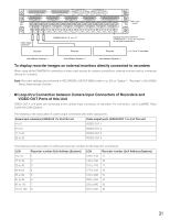
* The following are abbreviations. • Unit Address S: Unit Address (System): • Unit Address C: Unit Address (Controller) Video Output Board 2 Video Output Board 1 DATA 4 DATA 3 HDR4/TMNL8 HDR3/TMNL7 HDR2/TMNL4 HDR1/TMNL3 DATA 2 TMNL6 TMNL2 DATA 1 TMNL5 TMNL1/PS DATA TERM.ON ON TERM.OFF MODE MODE MODE switch settings Line termination: ON Line termination: OFF ON 12 ON 12 (#2: ON) (#2: OFF) Note: Normally, set #2 to ON. 4 3 MODE DATA MODE 2 MODE DATA 1 OFF ON MODE OUT EXTENSION 1 IN TERM. OUT X-3 16 15 14 13 12 11 10 9 8 7 6 5 4 3 2 1 MONITOR OUT OUT X-2 ALARM OUT 2 ALARM OUT 1 VS IN Video Output Board 2 Video Output Board 1 DATA 4 DATA 3 HDR4/TMNL8 HDR3/TMNL7 HDR2/TMNL4 HDR1/TMNL3 DATA 2 TMNL6 TMNL2 DATA 1 TMNL5 TMNL1/PS DATA TERM.ON ON TERM.OFF MODE MODE 4 MODE DATA VS OUT (THRU) VS OUT SERIAL 3 2 1 Video Output Board 1 Only OUT X-1 OFF ON MODE MODE DATA MODE OUT EXTENSION 1 IN TERM. OUT X-3 Video Output Board 2 16 15 14 13 12 11 10 9 8 MONITOR OUT ALARM OUT 2 ALARM OUT 1 7 6 5 4 VS IN VS OUT (THRU) VS OUT SERIAL 3 2 1 OUT X-2 Video Output Board 1 Only OUT X-1 Video Output Board 1 Recorder Unit Address S: 9 Unit Address C: 1 LCN (Logical Camera Number): 129 to 144 Line termination: OFF Recorder Unit Address S: 10 LCN (Logical Camera Unit Address C: 2 Number): 145 to 160 Line termination: OFF Recorder Unit Address S: 11 Unit Address C: 3 LCN (Logical Camera Number): 161 to 176 Line termination: OFF Recorder Unit Address S: 12 Unit Address C: 4 LCN (Logical Camera Number): 177 to 192 Line termination: ON Recorder Unit Address S: 13 Unit Address C: 1 LCN (Logical Camera Number): 193 to 208 Line termination: OFF Recorder Unit Address S: 14 LCN (Logical Camera Unit Address C: 2 Number): 209 to 224 Line termination: OFF Recorder Unit Address S: 15 Unit Address C: 3 LCN (Logical Camera Number): 225 to 240 Line termination: OFF Recorder Unit Address S: 16 LCN (Logical Camera Unit Address C: 4 Number): 241 to 256 Line termination: ON Recorder Unit Address S: 5 Unit Address C: 1 LCN (Logical Camera Number) : 65 to 80 Line termination: OFF Recorder Unit Address S: 6 Unit Address C: 2 LCN (Logical Camera Number) : 81 to 96 Line termination: OFF Recorder Unit Address S: 7 Unit Address C: 3 LCN (Logical Camera Number) : 97 to 112 Line termination: OFF Recorder 3 1 1 SERIAL ALARM 4 2 AUDIO IN AUDIO OUT CASCADE OUT 2 MONITOR OUT CASCADE IN MONITOR (VGA) ALARM/CONTROL 16 15 14 13 12 11 10 9 8 7 IN OUT 16 15 14 13 12 11 10 9 8 7 VIDEO MODE 2 1 COPY 1 DATA 6 5 RS485(CAMERA) 10/100BASE-T EXT STORAGE 4 3 2 1 6 5 4 3 2 1 SIGNAL GND POWER AC IN Recorder Unit Address S: 1 Unit Address C: 1 LCN (Logical Camera Number): 1 to 16 Line termination: OFF 3 1 1 SERIAL ALARM 4 2 AUDIO IN AUDIO OUT CASCADE OUT 2 MONITOR OUT CASCADE IN MONITOR (VGA) ALARM/CONTROL 16 15 14 13 12 11 10 9 8 7 IN OUT 16 15 14 13 12 11 10 9 8 7 VIDEO MODE 2 1 COPY 1 DATA 6 5 RS485(CAMERA) 10/100BASE-T EXT STORAGE 4 3 2 1 6 5 4 3 2 1 SIGNAL GND POWER AC IN Recorder Unit Address S: 2 Unit Address C: 2 LCN (Logical Camera Number): 17 to 32 Line termination: OFF 3 1 1 SERIAL ALARM 4 2 AUDIO IN AUDIO OUT CASCADE OUT 2 MONITOR OUT CASCADE IN MONITOR (VGA) ALARM/CONTROL 16 15 14 13 12 11 10 9 8 7 IN OUT 16 15 14 13 12 11 10 9 8 7 VIDEO MODE 2 1 COPY 1 DATA 6 5 RS485(CAMERA) 10/100BASE-T EXT STORAGE 4 3 2 1 6 5 4 3 2 1 SIGNAL GND POWER AC IN Recorder Unit Address S: 3 Unit Address C: 3 LCN (Logical Camera Number): 33 to 48 Line termination: OFF Unit Address S: 8 Unit Address C: 4 LCN (Logical Camera Number) : 113 to 128 Line termination: ON MODE switches ON (#7: ON) (#8: OFF) 123456 78 3 1 1 SERIAL ALARM 4 2 AUDIO IN AUDIO OUT CASCADE OUT 2 MONITOR OUT CASCADE IN MONITOR (VGA) ALARM/CONTROL 16 15 14 13 12 11 10 9 8 7 IN OUT 16 15 14 13 12 11 10 9 8 7 VIDEO MODE 2 1 COPY 1 DATA 6 5 RS485(CAMERA) 10/100BASE-T EXT STORAGE 4 3 2 1 6 5 4 3 2 1 SIGNAL GND POWER AC IN Recorder Unit Address S: 4 Unit Address C: 4 LCN (Logical Camera Number): 49 to 64 Line termination: ON 33
-
 1
1 -
2
-
3
-
4
-
5
-
6
-
7
-
8
-
9
-
10
-
11
-
12
-
13
-
14
-
15
-
16
-
17
-
18
-
19
-
20
-
21
-
22
-
23
-
24
-
25
-
26
-
27
-
 28
28 -
 29
29 -
 30
30 -
 31
31 -
 32
32 -
 33
33 -
 34
34 -
 35
35 -
 36
36 -
 37
37 -
 38
38 -
39
-
40
-
41
-
42
-
43
-
44
-
45
-
46
-
47
-
48
-
49
-
50
-
51
-
52
-
53
-
54
-
55
-
56
-
57
-
58
-
59
-
60
-
61
-
62
-
63
-
64
-
65
-
66
-
67
-
68
-
69
-
70
-
71
-
72
-
73
-
74
-
75
-
76
-
77
-
78
-
79
-
80
-
81
-
82
-
83
-
84
-
85
-
86
-
87
-
88
-
89
-
90
-
91
-
92
-
93
-
94
-
95
-
96
-
97
-
98
 |
 |
