Panasonic WJSX650 WJSX650 User Guide - Page 86
Connections Of Matrix Switchers (wj-sx650 Series) And A Ps-data System Controller
 |
View all Panasonic WJSX650 manuals
Add to My Manuals
Save this manual to your list of manuals |
Page 86 highlights
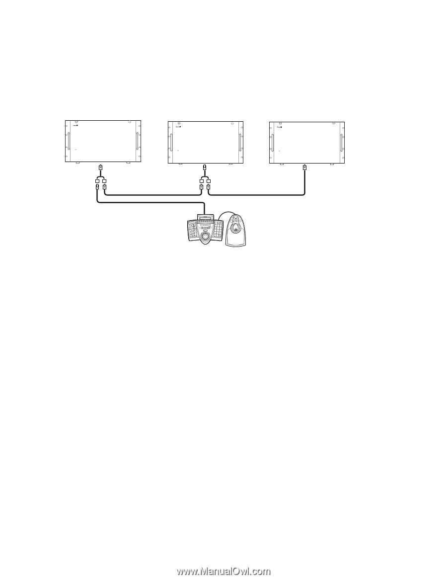
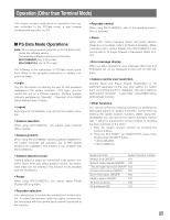
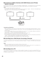
I Connections of Matrix Switchers (WJ-SX650 Series) and a PS·Data System Controller By connecting a PS·Data system controller (WV-CU950/650, CONTROLLER NO.: 1) to the DATA ports of the units with Cable Kit WV-CA48/10K, you can control these units from the system controller. (Refer to p. 35 for details on connections.) Notes: • Connect Cable Kit WV-CA48/10K to the DATA 1 port. • Set the DATA 1 port of each unit to PSD. Setting changes are performed in "System" - "DATA Port" of WJ-SX650 Series Administrator Console or DATA PORT (refer to p. 52) of SETUP MENU. Unit Address: 1 Unit Address: 2 Unit Address: 3 OPERATE OPERATE LED WILL BLINK IF COOLING FAN MALFUNCTIONS 650 Matrix Switcher WJ-SX OPERATE OPERATE LED WILL BLINK IF COOLING FAN MALFUNCTIONS 650 Matrix Switcher WJ-SX Cable Kit WV-CA48/10K OPERATE OPERATE LED WILL BLINK IF COOLING FAN MALFUNCTIONS 650 Matrix Switcher WJ-SX SYSTEM CONTROLLER 123 456 789 0 A B CONTROLLER NO.: 1 Connections and Operations • When controlling two or more units from a PS·Data system controller, you need to select a unit before operation. To select a unit, enter a unit address by pressing the numeric buttons. Then, press the RECORDER/UNIT button while holding down the SHIFT button. • The unit address setting of each unit must be different from each other. The unit address settings are performed in "Communication" - "PS.Data" of WJ-SX650 Series Administrator Console. • When an alarm occurs to a unit, other units will accept the alarm as a serial alarm input. • User level settings for alarm suspension must be the same within all the units. • The LCN settings must be different among all the units. (Up to LCN 999 are available.) The LCN settings are performed in "System" - "Logical Camera Number" of WJ-SX650 Series Administrator Console. • When activating AUTO RESET, set the parameter to 3 sec or longer. (Refer to p.49.) I Controlling from a Web Browser Accessing a Recorder If a recorder is connected to the unit, you can control cameras using a web browser of a PC accessing the recorder. You can set priority for web browser control. Priority setting is performed in "Operator" - "Operator" of WJ-SX650 Series Administrator Console. Notes: • Refer to the operating instructions of recorder for details on browser control. • Regardless of priority setting, during the recorder control from a system controller, camera control is not available from a web browser accessing recorders connected to the same DATA port in the daisy chain. I Controlling from a PC You can perform the operations and functions of system controllers by logging into the system and sending RS-232C commands from a PC connected to the unit. Refer to Serial (RS-232C) Connector Command Reference (PDF file on the supplied CD-ROM) for available commands. 86
-
 1
1 -
2
-
3
-
4
-
5
-
6
-
7
-
8
-
9
-
10
-
11
-
12
-
13
-
14
-
15
-
16
-
17
-
18
-
19
-
20
-
21
-
22
-
23
-
24
-
25
-
26
-
27
-
28
-
29
-
30
-
31
-
32
-
33
-
34
-
35
-
36
-
37
-
38
-
39
-
40
-
41
-
42
-
43
-
44
-
45
-
46
-
47
-
48
-
49
-
50
-
51
-
52
-
53
-
54
-
55
-
56
-
57
-
58
-
59
-
60
-
61
-
62
-
63
-
64
-
65
-
66
-
67
-
68
-
69
-
70
-
71
-
72
-
73
-
74
-
75
-
76
-
77
-
78
-
79
-
80
-
 81
81 -
 82
82 -
 83
83 -
 84
84 -
 85
85 -
 86
86 -
 87
87 -
 88
88 -
 89
89 -
 90
90 -
 91
91 -
92
-
93
-
94
-
95
-
96
-
97
-
98
 |
 |