Panasonic WJSX650 WJSX650 User Guide - Page 16
Installations, Checking Board Composition - wj sx650u g
 |
View all Panasonic WJSX650 manuals
Add to My Manuals
Save this manual to your list of manuals |
Page 16 highlights
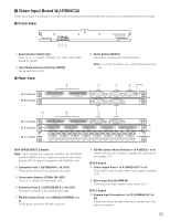
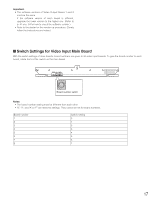
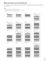
Installations CAUTION These servicing instructions are for use by qualified service personnel only. To reduce the risk of electric shock do not perform any servicing other than that contained in the operating instructions unless you are qualified to do so. The following is the installation flow of this unit. • Checking Board Composition • Switch Settings for Video Input Main Board (Refer to p. 17.) • Switch Settings for Video Output Main Board (Refer to p. 18.) • Mounting Video Input and Output Boards (Refer to p. 19.) • Board Mounting Procedure (Refer to p. 20.) • Installing the Main Unit (Refer to p. 21.) I Checking Board Composition By mounting additional video input and output boards, up to 256 cameras and 32 monitors can be connected to this unit. You will choose one of the composition types described in the following diagram. Check how many video input boards, video output boars, and card cages are required, according to the number of cameras and monitors. Note: Refer to p. 19 for the figures describing the composition types. Total numbers of cameras and recorders 1 to 32 33 to 64 65 to 96 97 to 128 129 to 160 161 to 192 193 to 224 225 to 256 Total number of monitors 1 to 16 17 to 32 1 to 16 17 to 32 1 to 16 17 to 32 1 to 16 17 to 32 1 to 16 17 to 32 1 to 16 17 to 32 1 to 16 17 to 32 1 to 16 17 to 32 Additional sets of video input board 0 0 1 1 2 3 3 3 4 4 5 6 6 6 7 7 Additional sets of video output board 0 1 0 1 0 1 0 1 0 1 0 1 0 1 0 1 Additional card cages 0 0 0 1 1 1 1 1 1 2 2 2 2 2 2 3 Composition type (Refer to p. 19.) Type 1 Type 2 Type 3 Type 4 Type 5 Type 6 Type 7 Type 8 Type 9 Type 10 Type 11 Type 12 Type 13 Type 14 Type 15 Type 16 Notes: • When using 9 or more recorders, 2 sets of additional video output board are required even if you use 16 or less monitors. • External monitors directly connected to recorders can be excluded from the total number of monitor in the diagram. • When connecting monitors directly to recorders, the total numbers of these recorders can be excluded from "Total number of cameras and recorders" in the diagram. • Use the following models for system expansion. Video input board: WJ-PB65C32 Video output board: WJ-PB65M16 Card Cage: WJ-SX650U • To connect Card Cage WJ-SX650U, Expansion Cable Kit WJ-CA65L07K (Option) or WJ-CA65L20K (Option) is required. • To record camera images by using a recorder, Dsub/BNC Video Cable WJ-CA68 (Option) is required. • The maximum set numbers of additional boards are as follows. Video input board: Max. 7 sets Video output board: Max. 1 sets Board sets exceeding these total numbers cannot be mounted even some expansion slots are unused. 16
-
 1
1 -
2
-
3
-
4
-
5
-
6
-
7
-
8
-
9
-
10
-
 11
11 -
 12
12 -
 13
13 -
 14
14 -
 15
15 -
 16
16 -
 17
17 -
 18
18 -
 19
19 -
 20
20 -
 21
21 -
22
-
23
-
24
-
25
-
26
-
27
-
28
-
29
-
30
-
31
-
32
-
33
-
34
-
35
-
36
-
37
-
38
-
39
-
40
-
41
-
42
-
43
-
44
-
45
-
46
-
47
-
48
-
49
-
50
-
51
-
52
-
53
-
54
-
55
-
56
-
57
-
58
-
59
-
60
-
61
-
62
-
63
-
64
-
65
-
66
-
67
-
68
-
69
-
70
-
71
-
72
-
73
-
74
-
75
-
76
-
77
-
78
-
79
-
80
-
81
-
82
-
83
-
84
-
85
-
86
-
87
-
88
-
89
-
90
-
91
-
92
-
93
-
94
-
95
-
96
-
97
-
98
 |
 |
