Panasonic WJSX650 WJSX650 User Guide - Page 9
Major Operating Controls And Their Functions, Wj-sx650 Matrix Switcher/wj-sx650u Card Cage - wj sx650 g
 |
View all Panasonic WJSX650 manuals
Add to My Manuals
Save this manual to your list of manuals |
Page 9 highlights
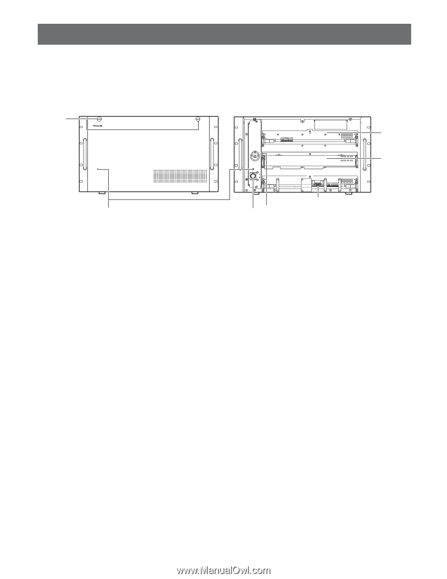
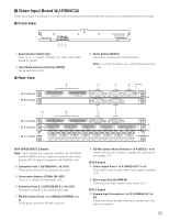
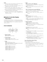
Major Operating Controls and Their Functions I WJ-SX650 Matrix Switcher/WJ-SX650U Card Cage G Front View w OPERATE OPERATE LED WILL BLINK IF COOLING FAN MALFUNCTIONS q 650 Matrix Switcher WJ-SX q Operation Indicator (OPERATE) • This indicator is lighting while power is supplied to the unit. • This indicator blinks when the cooling fan has a trouble. (Refer to p. 89.) w Front Panel Fixing Screws Before you press the power switch or install boards into the expansion slot, these screw are removed to detach the front panel e Power Switch r Expansion Slot Optional video input or output main board is installed. (Video Input Board WJ-PB65C32 or Video Output Board WJ-PB65M16) For WJ-SX650U, optional video input main board is installed. (Video Input Board WJ-PB65C32) PULL POWER ON OFF RESET No. MODE TEST RESET MODE t r y e Normally, do not touch. (Reserved for service personnel) This is the illustration of WJ-SX650. t Video Input Board* This is a video input main board. This board controls cameras and alarm sensors (door switch, etc.). Note: Refer to p. 11 WJ-PB65C32 Video Input Board for details. y Video Output Board* This is a video output main board. This board controls monitors and alarm output signals. Note: Refer to p. 12 WJ-PB65M16 Video Output Board for details. * For WJ-SX650U, t and y are expansion slots. 9
-
 1
1 -
2
-
3
-
 4
4 -
 5
5 -
 6
6 -
 7
7 -
 8
8 -
 9
9 -
 10
10 -
 11
11 -
 12
12 -
 13
13 -
 14
14 -
15
-
16
-
17
-
18
-
19
-
20
-
21
-
22
-
23
-
24
-
25
-
26
-
27
-
28
-
29
-
30
-
31
-
32
-
33
-
34
-
35
-
36
-
37
-
38
-
39
-
40
-
41
-
42
-
43
-
44
-
45
-
46
-
47
-
48
-
49
-
50
-
51
-
52
-
53
-
54
-
55
-
56
-
57
-
58
-
59
-
60
-
61
-
62
-
63
-
64
-
65
-
66
-
67
-
68
-
69
-
70
-
71
-
72
-
73
-
74
-
75
-
76
-
77
-
78
-
79
-
80
-
81
-
82
-
83
-
84
-
85
-
86
-
87
-
88
-
89
-
90
-
91
-
92
-
93
-
94
-
95
-
96
-
97
-
98
 |
 |