Panasonic WJSX650 WJSX650 User Guide - Page 30
RECORDER CONNECTION, Connection to Video Output Connectors of Recorders
 |
View all Panasonic WJSX650 manuals
Add to My Manuals
Save this manual to your list of manuals |
Page 30 highlights
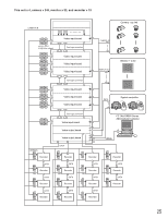
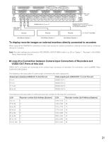
I Recorder Connection The following is a connection example to use recorders. Note: Use recorders with the following versions. • WJ-HD300 Series: Ver. 1.61 or later • WJ-HD300A Series: Ver. 3.10 or later G Connection to Video Output Connectors of Recorders To display recorder images on monitors connected to this unit When the video output connectors of recorders are connected to CAMERA IN connectors of this unit, recorder images can be displayed on Monitor 1 to 32. The following is the connection procedure. 1. Assign Unit Address (System) to the recorders. (Refer to p. 34 q.) Available unit addresses are 1 to 16. The unit address setting must be different from each other. 2. Decide the video input board to supply video input signals from recorder. Choose a video input board that has more unused connectors (CAMERA IN 17 to 32) than the recorder total number. Note: Only one video input board can be connected to the video output connector of recorders. 3. Connect the video output connectors (the monitor output 2 connector) of recorders and the CAMERA IN 17 to 32 connectors of the unit. Recorder number (Unit Address (System)) 1 2 3 4 5 6 7 8 CAMERA IN connector of video input board 32 31 30 29 28 27 26 25 Recorder number (Unit Address (System)) 9 10 11 12 13 14 15 16 CAMERA IN connector of video input board 24 23 22 21 20 19 18 17 Note: To supply video input signals from recorders to video input boards, perform the settings surely in RECORDER of SETUP MENU (refer to p. 50) or "System" - "Recorder" of WJ-SX650 Series Administrator Console. 30
-
 1
1 -
2
-
3
-
4
-
5
-
6
-
7
-
8
-
9
-
10
-
11
-
12
-
13
-
14
-
15
-
16
-
17
-
18
-
19
-
20
-
21
-
22
-
23
-
24
-
 25
25 -
 26
26 -
 27
27 -
 28
28 -
 29
29 -
 30
30 -
 31
31 -
 32
32 -
 33
33 -
 34
34 -
 35
35 -
36
-
37
-
38
-
39
-
40
-
41
-
42
-
43
-
44
-
45
-
46
-
47
-
48
-
49
-
50
-
51
-
52
-
53
-
54
-
55
-
56
-
57
-
58
-
59
-
60
-
61
-
62
-
63
-
64
-
65
-
66
-
67
-
68
-
69
-
70
-
71
-
72
-
73
-
74
-
75
-
76
-
77
-
78
-
79
-
80
-
81
-
82
-
83
-
84
-
85
-
86
-
87
-
88
-
89
-
90
-
91
-
92
-
93
-
94
-
95
-
96
-
97
-
98
 |
 |
