Panasonic WJSX650 WJSX650 User Guide - Page 28
Connection, Daisy Chain Connection
 |
View all Panasonic WJSX650 manuals
Add to My Manuals
Save this manual to your list of manuals |
Page 28 highlights
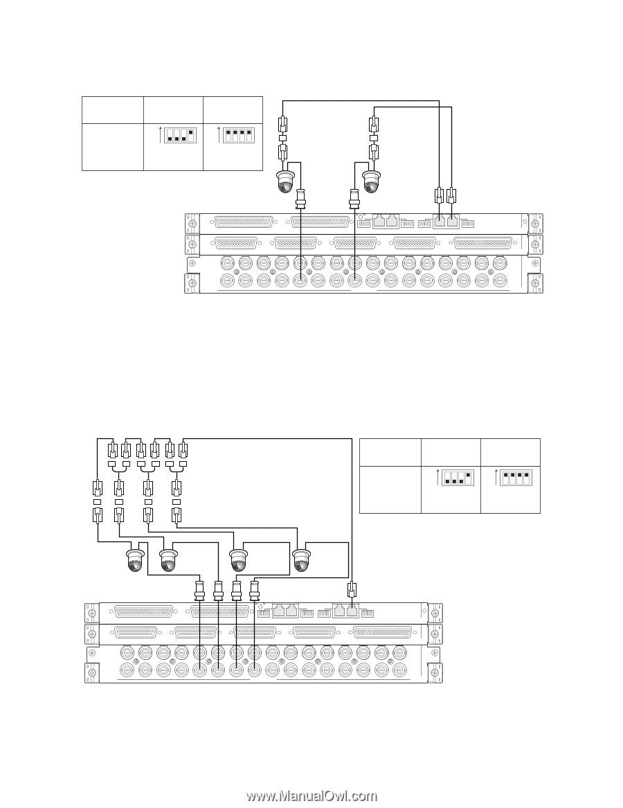
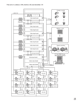
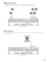
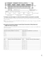
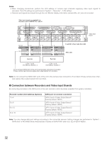
G 1:1 Connection One camera is connected to one RS-485 (CAMERA) port. Example: RS-485 cameras are connected to the CAMERA IN 9 and 12 connectors. Connector RS485 (CAMERA) 1 RS485 (CAMERA) 2 4-wire 2-wire communication communication ON ON 1234 (SW#4: ON) 1234 (SW#1 to 4: ON) MODE switch settings Unit number: 1 Line termination: ON Junction Unit WV-CA48/JN RS-485 cable Unit number: 1 Line termination: ON 4 3 2 1 EXTENSION 3 IN EXTENSION 2 IN MODE RS485 (CAMERA) MODE MODE RS485 (CAMERA) MODE IN C-3 VIDEO OUT 4 VIDEO OUT 3 VIDEO OUT 2 VIDEO OUT 1 ALARM IN IN X-2 32 31 30 29 28 27 26 25 24 23 22 21 20 19 18 17 16 15 14 13 12 11 10 9 8 7 6 5 4 3 2 1 CAMERA IN IN X-1 Video input rear boards Note: Do not use unit numbers other than 1 to 8 for individual cameras. (Refer to the operating instructions of camera for setting.) G Daisy Chain Connection Two or more cameras can be connected to one RS-485 (CAMERA) port. Up to 8 cameras are available. Example: RS-485 cameras are connected to the CAMERA IN 9 to 12 connectors Unit number: 4 Line termination: ON Daisy Chain Connection Kit WV-CA48/10K Junction Unit WV-CA48/JN RS-485 cable Connector RS485 (CAMERA) 1 4-wire 2-wire communication communication ON ON 1234 (SW#4: ON) 1234 (SW#1 to 4: ON) MODE switch settings Unit number: 3 Line termination: OFF Unit number: 2 Line termination: OFF Unit number: 1 Line termination: OFF 4 3 2 1 EXTENSION 3 IN EXTENSION 2 IN MODE RS485 (CAMERA) MODE MODE RS485 (CAMERA) MODE IN C-3 VIDEO OUT 4 VIDEO OUT 3 VIDEO OUT 2 VIDEO OUT 1 ALARM IN IN X-2 32 31 30 29 28 27 26 25 24 23 22 21 20 19 18 17 16 15 14 13 12 11 10 9 8 7 6 5 4 3 2 1 CAMERA IN IN X-1 Video input rear boards Notes: • Among cameras connected to an RS485 (CAMERA) port in the daisy chain (4-wire communication), only one camera can activate camera alarms. • Do not use unit numbers other than 1 to 8 for individual cameras. (Refer to the operating instructions of camera for setting.) • Do not set the same unit numbers for more than one camera in an RS-485 chain. 28
-
 1
1 -
2
-
3
-
4
-
5
-
6
-
7
-
8
-
9
-
10
-
11
-
12
-
13
-
14
-
15
-
16
-
17
-
18
-
19
-
20
-
21
-
22
-
 23
23 -
 24
24 -
 25
25 -
 26
26 -
 27
27 -
 28
28 -
 29
29 -
 30
30 -
 31
31 -
 32
32 -
 33
33 -
34
-
35
-
36
-
37
-
38
-
39
-
40
-
41
-
42
-
43
-
44
-
45
-
46
-
47
-
48
-
49
-
50
-
51
-
52
-
53
-
54
-
55
-
56
-
57
-
58
-
59
-
60
-
61
-
62
-
63
-
64
-
65
-
66
-
67
-
68
-
69
-
70
-
71
-
72
-
73
-
74
-
75
-
76
-
77
-
78
-
79
-
80
-
81
-
82
-
83
-
84
-
85
-
86
-
87
-
88
-
89
-
90
-
91
-
92
-
93
-
94
-
95
-
96
-
97
-
98
 |
 |