Panasonic WJSX650 WJSX650 User Guide - Page 23
Basic System Connections
 |
View all Panasonic WJSX650 manuals
Add to My Manuals
Save this manual to your list of manuals |
Page 23 highlights
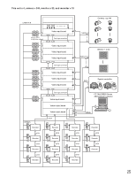
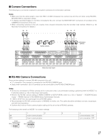
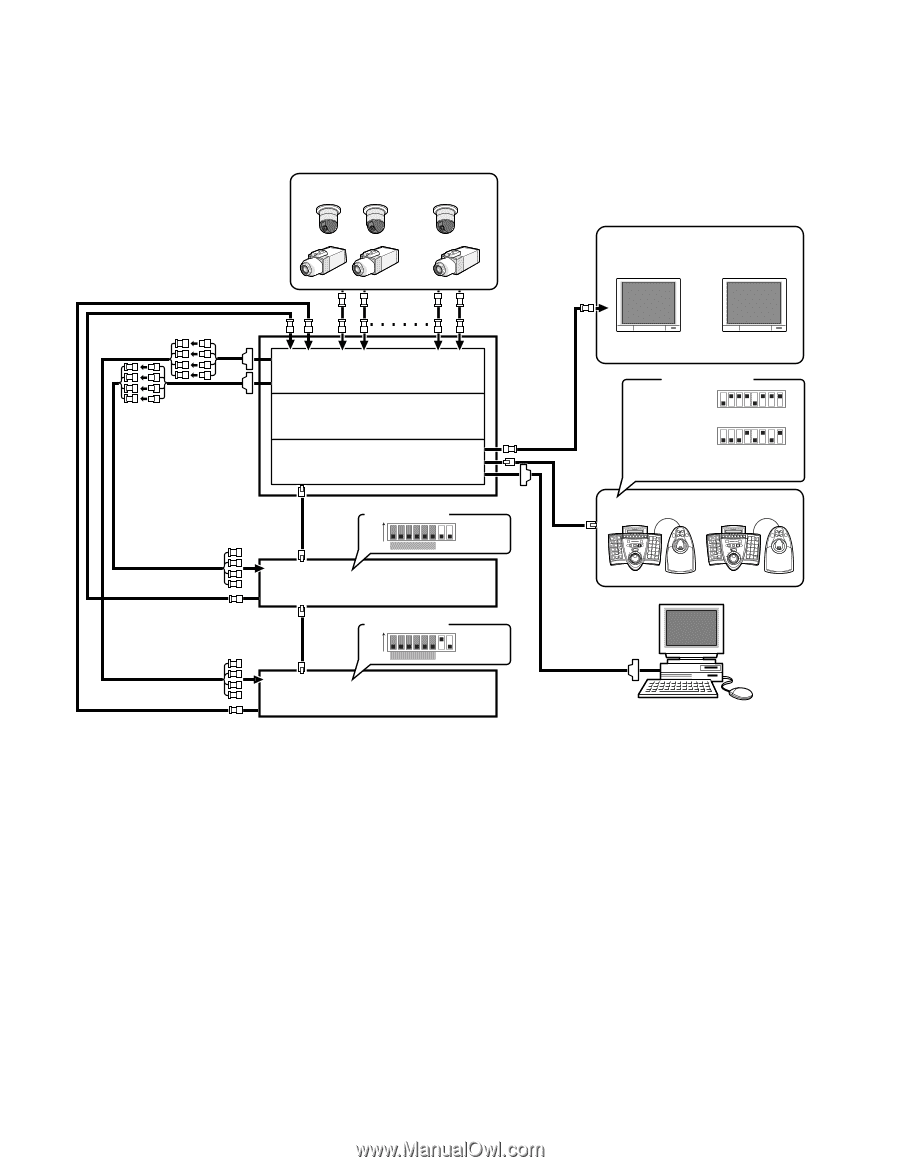
I Basic System Connections The following is a connection example to use one unit. This unit x 1, camera x 30, monitor x 16, and recorder x 2 VIDEO OUT (Loop-thru output) CAMERA IN MONITOR OUT CAMERA IN MONITOR OUT Camera 1 to 30 ~ ~ CAMERA IN Monitor 1 to 16 ~ Video input board Expansion slot Video output board MONITOR OUT DATA MODE switches ON 123456 78 (#7: OFF) (#8: OFF) Recorder DATA MODE switches WV-CU950/650 123456 78 WV-CU360C/CJ 123456 78 Terminal mode, Line termination: ON System controller SYSTEM CONTROLLER 123 456 789 0 A B SYSTEM CONTROLLER 123 456 789 0 A B MODE switches ON 123456 78 (#7: ON) (#8: OFF) Recorder SERIAL PC (WJ-SX650 Series Administrator Console) 23
-
 1
1 -
2
-
3
-
4
-
5
-
6
-
7
-
8
-
9
-
10
-
11
-
12
-
13
-
14
-
15
-
16
-
17
-
 18
18 -
 19
19 -
 20
20 -
 21
21 -
 22
22 -
 23
23 -
 24
24 -
 25
25 -
 26
26 -
 27
27 -
 28
28 -
29
-
30
-
31
-
32
-
33
-
34
-
35
-
36
-
37
-
38
-
39
-
40
-
41
-
42
-
43
-
44
-
45
-
46
-
47
-
48
-
49
-
50
-
51
-
52
-
53
-
54
-
55
-
56
-
57
-
58
-
59
-
60
-
61
-
62
-
63
-
64
-
65
-
66
-
67
-
68
-
69
-
70
-
71
-
72
-
73
-
74
-
75
-
76
-
77
-
78
-
79
-
80
-
81
-
82
-
83
-
84
-
85
-
86
-
87
-
88
-
89
-
90
-
91
-
92
-
93
-
94
-
95
-
96
-
97
-
98
 |
 |
23
■
Basic System Connections
The following is a connection example to use one unit.
This unit x 1, camera x 30, monitor x 16, and recorder x 2
Video input board
Expansion slot
Video output board
1
3
2
4
6
5
7
9
8
0
1
3
2
4
6
5
7
9
8
0
System controller
SERIAL
DATA
DATA
CAMERA IN
CAMERA IN
CAMERA IN
MONITOR OUT
MONITOR OUT
MONITOR
OUT
Recorder
Recorder
~
~
~
PC (WJ-SX650 Series
Administrator Console)
78
ON
6
12345
78
6
12345
78
6
12345
78
ON
6
12345
Camera 1 to 30
Monitor 1 to 16
VIDEO OUT (Loop-thru output)
(#7: ON)
(#8: OFF)
(#7: OFF)
(#8: OFF)
MODE switches
MODE switches
MODE switches
WV-CU950/650
WV-CU360C/CJ
Terminal mode,
Line termination: ON