Panasonic WJSX650 WJSX650 User Guide - Page 32
Connection between Recorders and Video Input Boards, Recorder number Unit Address System
 |
View all Panasonic WJSX650 manuals
Add to My Manuals
Save this manual to your list of manuals |
Page 32 highlights
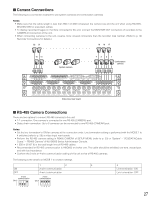
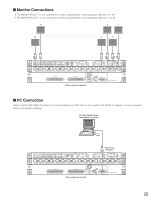
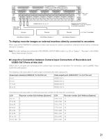
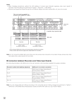
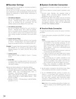
Notes: • When changing connections, perform the LCN settings of camera input channels supplying video input signals to recorders. The LCN settings are performed in "System" - "Recorder" - "LCN setting". • Camera input signals are looped through the unit. Monitor display information (camera title, etc.) are not recorded. Video input signals are supplied from recorders to the CAMERA IN 31 and 32. EXTENSION 3 IN 4 3 2 1 EXTENSION 2 IN MODE RS485 (CAMERA) MODE MODE RS485 (CAMERA) MODE IN C-3 VIDEO OUT 4 VIDEO OUT 3 VIDEO OUT 2 VIDEO OUT 1 ALARM IN IN X-2 32 31 30 29 28 27 26 25 24 23 22 21 20 19 18 17 Video input board 32 31 30 16 15 14 13 12 11 10 9 8 7 6 5 4 3 2 1 CAMERA IN IN X-1 25 24 17 16 98 D-sub/BNC Video Cable WJ-CA68 1 BNC cable Recorder Recorder LCN: 17 to 32 Unit Address (System): 2 LCN: 1 to 16 Unit Address (System): 1 Do not connect VIDEO OUT of the unit to camera input connectors of recorders if these camera input channels supply video output signals from recorders. Note: Do not connect the VIDEO OUT ports of the unit to the camera input connectors of recorders if these camera input channels supply video output signals from recorders. G Connection between Recorders and Video Input Boards By connecting recorders to the DATA ports of this unit, recorder control becomes available from system controllers. Recorder number (Unit Address (System)) 1 to 4 5 to 8 9 to 12 13 to 16 DATA port for recorder connection DATA 3 port of Video Output Board 1 (Factory default: HDR1) DATA 4 port of Video Output Board 1 (Factory default: HDR2) DATA 3 port of Video Output Board 2 (Factory default: HDR3) DATA 4 port of Video Output Board 2 (Factory default: HDR4) Note: You can change data port settings according to the connected devices. Setting changes are performed in "System" - "DATA Port" of WJ-SX650 Series Administrator Console or DATA PORT (refer to p. 52) of SETUP MENU. 32
-
 1
1 -
2
-
3
-
4
-
5
-
6
-
7
-
8
-
9
-
10
-
11
-
12
-
13
-
14
-
15
-
16
-
17
-
18
-
19
-
20
-
21
-
22
-
23
-
24
-
25
-
26
-
 27
27 -
 28
28 -
 29
29 -
 30
30 -
 31
31 -
 32
32 -
 33
33 -
 34
34 -
 35
35 -
 36
36 -
 37
37 -
38
-
39
-
40
-
41
-
42
-
43
-
44
-
45
-
46
-
47
-
48
-
49
-
50
-
51
-
52
-
53
-
54
-
55
-
56
-
57
-
58
-
59
-
60
-
61
-
62
-
63
-
64
-
65
-
66
-
67
-
68
-
69
-
70
-
71
-
72
-
73
-
74
-
75
-
76
-
77
-
78
-
79
-
80
-
81
-
82
-
83
-
84
-
85
-
86
-
87
-
88
-
89
-
90
-
91
-
92
-
93
-
94
-
95
-
96
-
97
-
98
 |
 |
