Panasonic WJSX650 WJSX650 User Guide - Page 42
TOOLTIP DETAILS, Reference No., Explanation, Notes
 |
View all Panasonic WJSX650 manuals
Add to My Manuals
Save this manual to your list of manuals |
Page 42 highlights
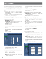
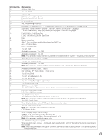
Notes: • Do not edit the setup data files by using text editors, etc. You may become unable to open the setup data files. • To perform q, w, and u, this unit needs to be connected to the PC with an RS-232C cable. I Tooltip Details When you point the cursor on a button or pull-down menu, a tooltip appears. Tool tips that have additional explanations include reference numbers such as "∗1". Refer to the following diagram for these additional explanations. Reference No. 1 2 3 4 5 6 7 Explanation 1 to 8: Port No. 4800 bps, 9600 bps, 19200 bps, 38400 bps: Transmission speed Character entry limit: 20 characters Available characters: Alphanumeric characters and symbols 1,2: Level 1 to 8: Video input board No. Available parameters: Blank, 1 to 999 ON: Use OFF: Not use Note: ON is not available for recorders when camera input channels are set for RS-485 cameras. To acti- vate recorder connections, set "--" for the setting items of "RS485" and "Unit number" in "System" - "VD2/DATA/Cable Comp." - "RS485 Camera". 8 Available parameters: Blank, 1 to 999 Note: Select the camera numbers that has been set in "System" - "Logical Camera Number". 9 [DATA1] TMNL1, PSD: Port type [DATA1] TMNL2: Port type [DATA3] TMNL3, HDR1: Port type [DATA4] TMNL4, HDR 2: Port type [DATA5] TMNL 5: Port type [DATA6] TMNL 6: Port type [DATA7] TMNL7, HDR3: Port type [DATA8] TMNL8, HDR4: Port type 10 4800 bps, 9600 bps, 19200 bps: Transmission speed To change the transmission speed, conform the settings of this unit to that of connected devices. 11 [Input Board 1] 1 to 4: Port number [Input Board 2] 5 to 8: Port number [Input Board 3] 9 to 12: Port number [Input Board 4] 13 to 16: Port number [Input Board 5] 17 to 20: Port number [Input Board 6] 21 to 24: Port number [Input Board 7] 25 to 28: Port number [Input Board 8] 29 to 32: Port number Note: Port numbers cannot be set for camera input channels accepting video input signals from recorders. To activate RS-485 camera connections, set "OFF" for Control of these recorders in "System" - "Recorder". 12 1 to 8: Camera unit number Note: Camera unit number cannot be set for camera input channels accepting video input signals from recorders. To activate RS-485 camera connections, set "OFF" for Control of these recorders in "System" - "Recorder". 13 ON: Overlap OFF: Not overlap 14 S: Less than 400 m {1 300 ft} M: 400 m {1 300 ft} to 700 m {2 300 ft} L: 700 m {2 300 ft} to 900 m {3 000 ft} Note: Refer to p. 27 for details on the cable length. 42
-
 1
1 -
2
-
3
-
4
-
5
-
6
-
7
-
8
-
9
-
10
-
11
-
12
-
13
-
14
-
15
-
16
-
17
-
18
-
19
-
20
-
21
-
22
-
23
-
24
-
25
-
26
-
27
-
28
-
29
-
30
-
31
-
32
-
33
-
34
-
35
-
36
-
 37
37 -
 38
38 -
 39
39 -
 40
40 -
 41
41 -
 42
42 -
 43
43 -
 44
44 -
 45
45 -
 46
46 -
 47
47 -
48
-
49
-
50
-
51
-
52
-
53
-
54
-
55
-
56
-
57
-
58
-
59
-
60
-
61
-
62
-
63
-
64
-
65
-
66
-
67
-
68
-
69
-
70
-
71
-
72
-
73
-
74
-
75
-
76
-
77
-
78
-
79
-
80
-
81
-
82
-
83
-
84
-
85
-
86
-
87
-
88
-
89
-
90
-
91
-
92
-
93
-
94
-
95
-
96
-
97
-
98
 |
 |
