Panasonic WJSX650 WJSX650 User Guide - Page 53
Vd2/data/cable Compensation, Rs485 Camera Menu, Input Board, Cable, Rs485
 |
View all Panasonic WJSX650 manuals
Add to My Manuals
Save this manual to your list of manuals |
Page 53 highlights
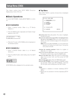
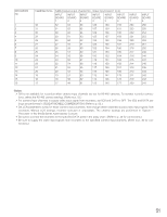
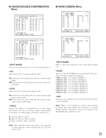
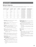
G VD2/DATA/CABLE COMPENSATION Menu 530 VD2/DATA/CABLE COMPENSATION 1 of 2 INPUT BOARD=8 CAM VD2 DATA CABLE CAM VD2 DATA CABLE 225 ON OFF S 233 ON OFF S 226 ON OFF M 234 ON OFF S 227 ON OFF L 235 ON OFF S 228 ON OFF S 236 ON OFF S 229 ON OFF M 237 ON ON S 230 ON OFF L 238 ON ON S 231 ON OFF S 239 ON ON S 232 ON OFF S 240 ON ON S CAM=CAMERA IN DATA:CAMERA CONTROL SIGNAL 530 VD2/DATA/CABLE COMPENSATION 2 of 2 INPUT BOARD=8 CAM VD2 DATA CABLE CAM VD2 DATA CABLE 241 ON OFF S 249 OFF OFF S 242 ON OFF M 250 OFF OFF S 243 OFF OFF L 251 OFF OFF S 244 OFF OFF S 252 OFF OFF S 245 OFF OFF M 253 OFF OFF S 246 OFF OFF L 254 OFF OFF S 247 OFF OFF S 255 OFF OFF S 248 OFF OFF S 256 OFF OFF S CAM=CAMERA IN DATA:CAMERA CONTROL SIGNAL • INPUT BOARD Select a video input board from 1 to 8. (The factory default is 1.) • VD2 Select ON or OFF. (The factory default is ON.) ON: Sends the VD2 timing pulse with the camera output signal. OFF: Not sends the VD2 timing pulse with the camera output signal. • DATA Select ON or OFF. (The factory default is ON.) ON: Sends the control data with the camera output signal via the coaxial cable. OFF: Not sends the control data with the camera output signal via the coaxial cable. • CABLE Perform the settings to compensate for the video signal transmission loss from the camera (cable compensation) according to the cable lengths. (The factory default is S.) S: Less than 400 m {1 300 ft} M: 400 m {1 300 ft} to 700 m {2 300 ft} L: 700 m {2 300 ft} to 900 m {3 000 ft} Note: When supplying video input signals from recorders or using cameras of other manufacturers, set VD2 and DATA to OFF. G RS485 CAMERA Menu 540 RS485 CAMERA INPUT BOARD=8 CAM RS485 UNIT 225 29 1 226 29 2 227 29 3 228 29 4 229 29 5 230 29 6 231 29 7 232 29 8 1 of 2 CAM RS485 233 30 234 30 235 30 236 30 237 238 239 240 UNIT 1 2 3 4 COMMUNICATION STATUS 19200/8/ NONE/1 CAM=CAMERA IN RS485=RS485(CAMERA) 540 RS485 CAMERA INPUT BOARD=8 CAM RS485 UNIT 241 31 1 242 32 1 243 244 245 246 247 248 2 of 2 CAM RS485 249 250 251 252 253 254 255 256 UNIT COMMUNICATION STATUS 19200/8/ NONE/1 CAM=CAMERA IN RS485=RS485(CAMERA) • INPUT BOARD Select a video input board from 1 to 8. (The factory default is 1.) • RS485 Select the RS-485 (CAMERA) port connecting RS-485 cameras. (The factory default is no settings.) CAM001 to 032: 1 to 4 (INPUT BOARD=1) CAM033 to 064: 5 to 8 (INPUT BOARD=2) CAM065 to 096: 9 to 12 (INPUT BOARD=3) CAM097 to 128: 13 to 16 (INPUT BOARD=4) CAM129 to 160: 17 to 20 (INPUT BOARD=5) CAM161 to 192: 21 to 24 (INPUT BOARD=6) CAM193 to 224: 25 to 28 (INPUT BOARD=7) CAM225 to 256: 29 to 32 (INPUT BOARD=8) • UNIT Select the unit numbers for the connected RS-485 cameras. 1 to 8 is available. Note: RS485 is not available for camera input channels accepting video input signals from recorders. To activate RS-485 camera connections, change the settings in the RECORDER menu. (Refer to p. 50.) 53
-
 1
1 -
2
-
3
-
4
-
5
-
6
-
7
-
8
-
9
-
10
-
11
-
12
-
13
-
14
-
15
-
16
-
17
-
18
-
19
-
20
-
21
-
22
-
23
-
24
-
25
-
26
-
27
-
28
-
29
-
30
-
31
-
32
-
33
-
34
-
35
-
36
-
37
-
38
-
39
-
40
-
41
-
42
-
43
-
44
-
45
-
46
-
47
-
 48
48 -
 49
49 -
 50
50 -
 51
51 -
 52
52 -
 53
53 -
 54
54 -
 55
55 -
 56
56 -
 57
57 -
 58
58 -
59
-
60
-
61
-
62
-
63
-
64
-
65
-
66
-
67
-
68
-
69
-
70
-
71
-
72
-
73
-
74
-
75
-
76
-
77
-
78
-
79
-
80
-
81
-
82
-
83
-
84
-
85
-
86
-
87
-
88
-
89
-
90
-
91
-
92
-
93
-
94
-
95
-
96
-
97
-
98
 |
 |
