Panasonic WJSX650 WJSX650 User Guide - Page 18
SWITCH SETTINGS FOR VIDEO OUTPUT MAIN BOARD, Front view of video output main board
 |
View all Panasonic WJSX650 manuals
Add to My Manuals
Save this manual to your list of manuals |
Page 18 highlights
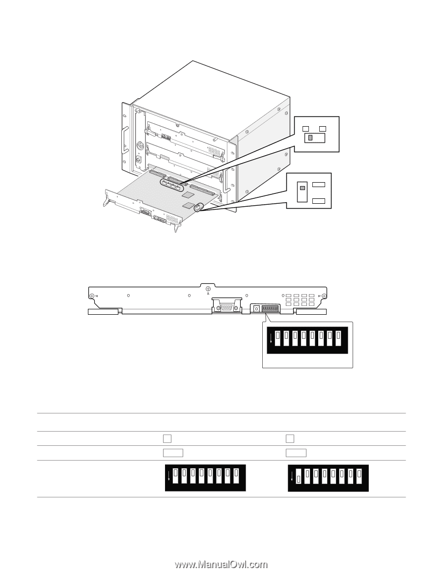
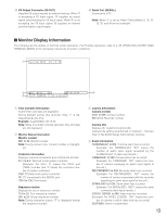
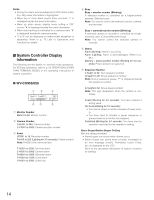
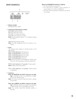
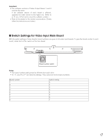
I Switch Settings for Video Output Main Board When mounting an additional video input board, up to 32 monitors can be connected to the unit. SW1, SW2, SW3, SW4 1 2 SW4006 HOST FUNC Front view of video output main board TEST RESET MODE OFF 1 2 3 4 5 6 7 8 MODE switches To identify Video Output Board 1 from Video Output Board 2, set the MODE switches (SW4004) and sliding switches (SW1, SW2, SW3, SW4, and SW4006) as follows. SW1, SW2, SW3, SW4 SW4006 MODE switches (SW4004) Video Output Board 1 (Monitor 1 to 16) 1 HOST Video Output Board 2 (Monitor 17 to 32) 2 FUNC OFF 1 2 3 4 5 6 7 8 OFF 1 2 3 4 5 6 7 8 Note: If the unit has only one Video Output Board, be sure to apply switch settings of Video Output Board 1. When the switch settings are incorrect, the unit may not work properly. 18
-
 1
1 -
2
-
3
-
4
-
5
-
6
-
7
-
8
-
9
-
10
-
11
-
12
-
 13
13 -
 14
14 -
 15
15 -
 16
16 -
 17
17 -
 18
18 -
 19
19 -
 20
20 -
 21
21 -
 22
22 -
 23
23 -
24
-
25
-
26
-
27
-
28
-
29
-
30
-
31
-
32
-
33
-
34
-
35
-
36
-
37
-
38
-
39
-
40
-
41
-
42
-
43
-
44
-
45
-
46
-
47
-
48
-
49
-
50
-
51
-
52
-
53
-
54
-
55
-
56
-
57
-
58
-
59
-
60
-
61
-
62
-
63
-
64
-
65
-
66
-
67
-
68
-
69
-
70
-
71
-
72
-
73
-
74
-
75
-
76
-
77
-
78
-
79
-
80
-
81
-
82
-
83
-
84
-
85
-
86
-
87
-
88
-
89
-
90
-
91
-
92
-
93
-
94
-
95
-
96
-
97
-
98
 |
 |