Panasonic WJSX650 WJSX650 User Guide - Page 35
Data Mode Connection, Notes, Example - matrix switcher wj sx650
 |
View all Panasonic WJSX650 manuals
Add to My Manuals
Save this manual to your list of manuals |
Page 35 highlights
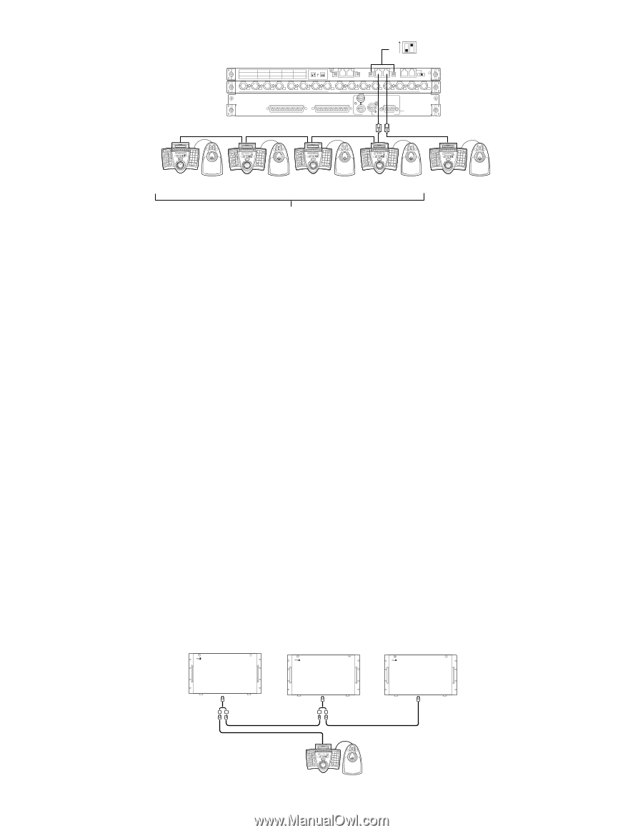
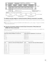
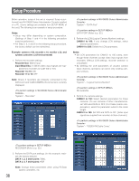
ON Line termination: ON (#2: ON) 12 Video Output Board 2 Video Output Board 1 DATA 4 DATA 3 HDR4/TMNL8 HDR3/TMNL7 HDR2/TMNL4 HDR1/TMNL3 DATA 2 TMNL6 TMNL2 DATA 1 TMNL5 TMNL1/PS DATA TERM.ON ON TERM.OFF MODE MODE 4 3 MODE DATA MODE 2 MODE DATA 1 OFF ON MODE OUT EXTENSION 1 IN TERM. OUT X-3 16 15 14 13 12 11 10 9 8 7 6 5 4 3 2 1 MONITOR OUT OUT X-2 ALARM OUT 2 ALARM OUT 1 VS IN VS OUT (THRU) VS OUT DATA2 SERIAL Video Output Board 1 Only OUT X-1 DATA1 Video output rear boards SYSTEM CONTROLLER 123 456 789 0 SYSTEM CONTROLLER 123 456 789 0 SYSTEM CONTROLLER 123 456 789 0 SYSTEM CONTROLLER 123 456 789 0 SYSTEM CONTROLLER 123 456 789 0 A B CONTROLLER NO.: 4 Line termination: ON CONTROLLER NO.: 3 Line termination: OFF CONTROLLER NO.: 2 Line termination: OFF CONTROLLER NO.: 1 Line termination: OFF CONTROLLER NO.: 1 Line termination: ON Daisy chain connection G PS·Data Mode Connection To apply the PS·Data mode, connect the system controllers as follows. 1. Connect the system controllers to the DATA 1 port of Video Output Board 1. Notes: • In the factory default, the DATA 1 port is set for the terminal mode connection. To apply the PS·Data mode connection, perform the DATA port settings in DATA PORT of SETUP MENU (refer to p. 52) or "System" - "DATA Port" of WJ-SX650 Series Administrator Console. • Both of terminal mode and PS·Data system controllers cannot be connected to the same DATA port. • DATA 1 port of Video Output Board 2 cannot be set for the PS·Data connection. • 1 200 m {3 937 ft} is the total length limit of cables (between this unit and the system controller at the chain end). • Up to 4 system controllers can be connected in the daisy chain. For system controllers in the daisy chain connection, operator registration is not available. (The same operator setting is applied for all the system controllers in the PS·Data daisy chain.) 2. If using only one system controller, set the MODE Switch #2 of DATA port connected to the system controller to ON. If using two or more system controllers in daisy chain connections, set the MODE Switch #2 of DATA port of the chain-end unit to ON. 3. Set the system controllers to the PS·Data mode. (Refer to the operating instructions of system controllers.) 4. Set the line termination of system controllers with the MODE switches. (Refer to the operating instructions of system controllers.) In the daisy chain connection, set the line termination of chain end system controller to ON. (Switch #5: ON) 5. In the daisy chain connection, set the CONTROLLER NO. switches of system controllers to 1 to 4. The switch setting must be different from each other. (Refer to the operating instructions of system controller for details on the CONTROLLER NO. switch setting.) Note: When using system controllers in the PS·Data mode, camera numbers that can be selected differ depending on system controller models. Example: WV-CU950/650: 1 to 999 WV-CU360C/CJ: 1 to 199 Select the system controller models that are applicable for your system composition. When using 200 or more cameras in the PS·Data mode, apply WVCU950/650. Unit Address: 1 Line termination OFF Unit Address: 2 Line termination OFF Unit Address: 3 Line termination ON OPERATE OPERATE LED WILL BLINK IF COOLING FAN MALFUNCTIONS 650 Matrix Switcher WJ-SX OPERATE OPERATE LED WILL BLINK IF COOLING FAN MALFUNCTIONS 650 Matrix Switcher WJ-SX Cable Kit WV-CA48/10K OPERATE OPERATE LED WILL BLINK IF COOLING FAN MALFUNCTIONS 650 Matrix Switcher WJ-SX SYSTEM CONTROLLER 123 456 789 0 A B CONTROLLER NO.: 1 35
-
 1
1 -
2
-
3
-
4
-
5
-
6
-
7
-
8
-
9
-
10
-
11
-
12
-
13
-
14
-
15
-
16
-
17
-
18
-
19
-
20
-
21
-
22
-
23
-
24
-
25
-
26
-
27
-
28
-
29
-
 30
30 -
 31
31 -
 32
32 -
 33
33 -
 34
34 -
 35
35 -
 36
36 -
 37
37 -
 38
38 -
 39
39 -
 40
40 -
41
-
42
-
43
-
44
-
45
-
46
-
47
-
48
-
49
-
50
-
51
-
52
-
53
-
54
-
55
-
56
-
57
-
58
-
59
-
60
-
61
-
62
-
63
-
64
-
65
-
66
-
67
-
68
-
69
-
70
-
71
-
72
-
73
-
74
-
75
-
76
-
77
-
78
-
79
-
80
-
81
-
82
-
83
-
84
-
85
-
86
-
87
-
88
-
89
-
90
-
91
-
92
-
93
-
94
-
95
-
96
-
97
-
98
 |
 |