Panasonic WJSX650 WJSX650 User Guide - Page 87
Glossary
 |
View all Panasonic WJSX650 manuals
Add to My Manuals
Save this manual to your list of manuals |
Page 87 highlights
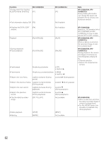
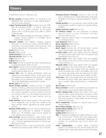
Glossary This document uses the following terms. Monitor number: Numbers (MON 1 to 32) given to the MONITOR OUT connectors of Video Output Board 1 and 2 for monitor selection Logical Camera number (LCN): Numbers set for the CAMERA IN connectors (CAM 1 to 256) of Video Input Board 1 to 8 for camera selection. As the factory default, LCN 1 to 256 are given to the CAM 1 to 256 in numerical order. Note: LCN setting changes are performed in "System" - "Logical Camera Number" of WJ-SX650 Series Administrator Console. Recorder number: Unit Address (System) numbers (Recorder 1 to 16) set for recorders in SETUP MENU of recorders for recorder selection. In this document, "Unit Address (System) 001" is mentioned as "Recorder 1". Level: Refer to p. 55. Priority: Refer to p. 55. Camera Access: Refer to p. 55. Recorder Access: Refer to p. 55. Login: Refer to p. 56. Logout: Refer to p. 56. Auto login: Function to log into the system automatically as a registered operator. Refer to p. 56. Auto logout: Function to log out of the system automatical- ly after no operations have been performed during the specified period. Refer to p. 56. Camera Title: Titles for camera identification, which are displayed on associated monitors, can be set up. Up to 20 characters are available for the camera title. Camera title setting will be performed in "Camera" - "Camera Title" of WJ-SX650 Series Administrator Console. Monitor lock: Refer to p. 57. Preset (Preset position): Camera's function to register camera monitoring positions (preset positions) associated with position numbers. By entering the preset position numbers, operators can move cameras to the preset positions. (Refer to p. 58.) Registered preset positions can be applied for event settings such as sequence. Home position: Default preset position. If the home position is registered, you can move the camera to the home position without specifying the preset position number. Auxiliary (AUX) control: You can control auxiliary devices (buzzer, etc.) connected to cameras or receivers. (Refer to p. 79.) Auxiliary control can be applied for event settings such as sequence. Auto tracking: Camera's function to detect motion of the image and track the moving object automatically. Refer to p. 71 and the operating instructions of cameras supporting this function. Patrol: Camera's function to learn and reproduce camera operations and picture quality. (Refer to pp. 71 and 78.) Cleaning (Camera Cleaning): Function to clean the slip ring to eliminate picture quality deterioration and noise. (Available for Panasonic cameras released in 1999 or later) Camera position: You can associate camera numbers with preset position numbers to register as camera positions (CAM-P). Camera selection recall: Refer to p. 58. All cameras control: You can deactivate all auxiliary devices at a time, or move all cameras to the home positions. Refer to p. 59. Spot: A selected camera image is continuously displayed on a selected monitor. Tour sequence: Refer to p. 62. Group sequence: Refer to p. 62. Group preset: Refer to p. 62. Alarm signal: General term for terminal alarm, camera alarm, recorder alarm, serial alarm, and video loss. Terminal alarm: Alarm input signals which are supplied from alarm sensors (door switch, etc.) to the alarm input (ALARM IN) ports of the unit. Camera alarm: Alarm input signals which are supplied from cameras to the unit by alarm sensors or cameras' motion detectors, etc. Recorder alarm: Alarm input signals which are supplied from recorders to the unit by video loss or VMD, etc. Serial alarm: Alarm input signals which are supplied as serial commands from a PC to the SERIAL port of the unit. Alarm commands which are input from the DATA ports set to PSD are also serial alarms. (Refer to p. 86.) Video loss: Alarm input signals which are supplied to the unit when the loss of video input signals are detected due to coaxial cable disconnections or camera troubles. Alarm event: Refer to p. 66. Alarm schedule: Function to schedule the period when no alarm events occur even with alarm input signals Monitor display mode: Display mode which can be activated for alarm events during alarm occurrence. There are three types of alarm modes: spot, tour sequence, and group sequence. These modes can be set separately for each monitor. Alarm suspension: Operation to suspend alarm occurrence to the unit. Alarm History Display: Refer to p. 69. System Status Display: Refer to p. 37. Timer event: Refer to p. 71. Camera event: Refer to p. 71. VD2: Timing pulse to display the images of Panasonic cameras on the monitor. If VD2 is set to ON, image switching unconformity can be prevented. (Depending on monitors, the unconformity may not be solved completely.) Cable compensation: If coaxial cables connected between the cameras and the unit are longer than the suitable length, video input signals may be attenuated. 87
-
 1
1 -
2
-
3
-
4
-
5
-
6
-
7
-
8
-
9
-
10
-
11
-
12
-
13
-
14
-
15
-
16
-
17
-
18
-
19
-
20
-
21
-
22
-
23
-
24
-
25
-
26
-
27
-
28
-
29
-
30
-
31
-
32
-
33
-
34
-
35
-
36
-
37
-
38
-
39
-
40
-
41
-
42
-
43
-
44
-
45
-
46
-
47
-
48
-
49
-
50
-
51
-
52
-
53
-
54
-
55
-
56
-
57
-
58
-
59
-
60
-
61
-
62
-
63
-
64
-
65
-
66
-
67
-
68
-
69
-
70
-
71
-
72
-
73
-
74
-
75
-
76
-
77
-
78
-
79
-
80
-
81
-
 82
82 -
 83
83 -
 84
84 -
 85
85 -
 86
86 -
 87
87 -
 88
88 -
 89
89 -
 90
90 -
 91
91 -
 92
92 -
93
-
94
-
95
-
96
-
97
-
98
 |
 |
