Panasonic WJSX650 WJSX650 User Guide - Page 20
Board Mounting Procedure, Notes
 |
View all Panasonic WJSX650 manuals
Add to My Manuals
Save this manual to your list of manuals |
Page 20 highlights
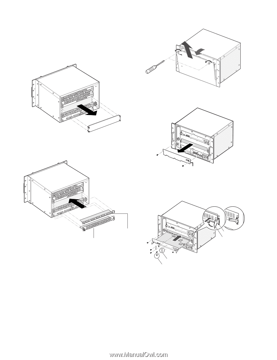
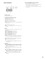
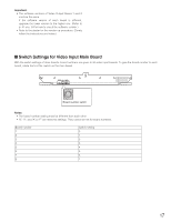
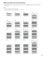
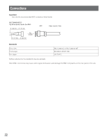
I Board Mounting Procedure The following example is the procedure to mount a network board into the expansion slot of the unit. Note: Before the procedure, power off the unit. 1. Remove the expansion slot panel from the rear side. Video Video Output Output Board Board 2 1 HHDDDRRA42T//TTAMM4NNLL84 HHDDDRRA31T//TTAMM3NNLL73 DATA 2 TMNL6 TMNL2 DATA 1 TMNTL1M/PNSLD5ATA TERM.ON TERM.OFF ON MODE MODE SIGNAL GND SIGNAL GND 3. Remove the front panel by loosening the screws. OPERATE 650 Matrix Switcher WJ-SX 4. Remove the blank panel from the front side. 2. Mount the rear boards into the expansion slot, and fix these boards with screws supplied to the rear boards. Video Video Output Output Board Board 2 1 HHDDDRRA42T//TTAMM4NNLL84 HHDDDRRA31T//TTAMM3NNLL73 DATA 2 TMNL6 TMNL2 DATA 1 TMNTL1M/PNSLD5ATA TERM.ON TERM.OFF ON MODE MODE SIGNAL GND SIGNAL GND Blank panel 5. Mount the main board by hooking the board stoppers on the board stopper angles at the front side, by pushing down the board stoppers, and by fixing the screws. IN X-2 board IN X-1 board Notes: • The board name (IN X-1, OUT X-1, etc.) is marked at the lower right corner of each board mounting angle. When mounting the rear boards, match the board names with the markings at board mounting angles. • To mount a set of video output board into the expansion slot, dismount the IN B-3 board, and then mount the OUT X-3. Board stopper angle Board stopper Hook the board stoppers on the board stopper angles, and push down the board stoppers. Fixing brackets* (x2) Screws* (x4) • Mount the main board into the slot. • Fix the board with the screws (x3). • Attach the fixing brackets (x2) with the screws (x4).* * Required when mounting a video output board (Not required when mounting a video input board) Notes: • Remove 3 screws surely at the arrow marking when dismounting. • When mounting, match the main board surely with the rear board. • When mounting, insert the main board surely into slits. • Do not hit the boards against the chassis of the unit. 20
-
 1
1 -
2
-
3
-
4
-
5
-
6
-
7
-
8
-
9
-
10
-
11
-
12
-
13
-
14
-
 15
15 -
 16
16 -
 17
17 -
 18
18 -
 19
19 -
 20
20 -
 21
21 -
 22
22 -
 23
23 -
 24
24 -
 25
25 -
26
-
27
-
28
-
29
-
30
-
31
-
32
-
33
-
34
-
35
-
36
-
37
-
38
-
39
-
40
-
41
-
42
-
43
-
44
-
45
-
46
-
47
-
48
-
49
-
50
-
51
-
52
-
53
-
54
-
55
-
56
-
57
-
58
-
59
-
60
-
61
-
62
-
63
-
64
-
65
-
66
-
67
-
68
-
69
-
70
-
71
-
72
-
73
-
74
-
75
-
76
-
77
-
78
-
79
-
80
-
81
-
82
-
83
-
84
-
85
-
86
-
87
-
88
-
89
-
90
-
91
-
92
-
93
-
94
-
95
-
96
-
97
-
98
 |
 |