Panasonic WJSX650 WJSX650 User Guide - Page 34
RECORDER SETTINGS, SYSTEM CONTROLLER CONNECTION, Terminal Mode Connection
 |
View all Panasonic WJSX650 manuals
Add to My Manuals
Save this manual to your list of manuals |
Page 34 highlights
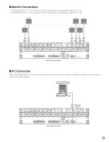
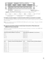
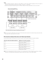
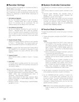
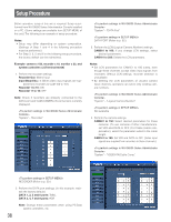
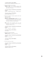
I Recorder Settings Be sure to perform the settings for connected recorders in SETUP MENU of recorders. You can set w to t after connections. However, you must set q separately for each recorder before connections. The settings are performed in SETUP MENU (Advanced) of each recorder. q Unit Address (System) Set the Unit Address (System) for each recorder in "Comm" - "PS.Data Setup". 001 to 016 are available. (Up to 16 recorders can be connected.) The unit address setting must be different from each other. w Unit Address (Controller) Set the Unit Address (Controller) for each recorder in "Comm" - "PS.Data Setup". 001 to 004 are available. (Up to 4 recorders can be connected to a DATA port.) The unit address setting must be different from each other among recorders connected to the same DATA port. e Camera Number Setup Perform the Camera Number setting for each recorder in "Comm" - "PS.Data Setup". The camera number settings must be identical as the LCN settings of this unit. Example: To supply video input signal from Camera 999 to the CAMERA IN 16 connector of Recorder 16 (Unit Address (System): 16), select CAM NO. 999 for CAM PORT 16. r Camera Control Select PSD for CAM1 to CAM16 in "Comm" - "Camera Control". t Event REC To activate alarm recording, perform the event recording settings surely. Refer to the operating instructions of recorders for details. Maintain the factory default for the following settings. • PSD User setting in "System" - "Basic Setup": ADMIN • Operation Mode setting of each Event Program - VMD, VIDEO LOSS, and Terminal/Command Alarm in "Schedule" - "Event Program": ALARM (When setting QUICK for REC Type, Operation Mode setting of Event REC in "SETUP MENU (Quick)" - "REC & Event": ALARM) • Settings in "Comm" - "PS.Data Setup" of SETUP MENU, except for q to e. I System Controller Connection The following is a connection example to use system controllers. There are two options to connect system controllers to this unit. • Terminal mode: Normally, this operation mode is applied. (When connecting System Controller WVCU360C/CJ, use Ver. 8.10 or later.) • PS·Data mode: When other system units are connected to this unit, and they are controlled by the same system controller, this operation mode is applied. This mode has operation restrictions. Refer to p. 85 OPERATION (OTHER THAN TERMINAL MODE). G Terminal Mode Connection To apply the terminal mode, connect the system controllers as follows. 1. Connect the system controllers to the DATA 1 to 4 ports of the unit. Notes: • In the factory default, the DATA 3 and 4 ports are set to HDR1 to 4 for recorder connection. To connect system controllers, perform the DATA port settings in DATA PORT of SETUP MENU (refer to p. 52) or "System" - "DATA Port" of WJ-SX650 Series Administrator Console. • Both of recorders and system controllers cannot be connected to the same DATA port. • 1 200 m {3 937 ft} is the total length limit of cables (between this unit and the system controller at the chain end). • By connecting up to 4 system controllers to one DATA port in the daisy chain, up to 16 system controllers are available in the system. (Up to 16 system controllers can log into the system at a time.) • Daisy chain connection is available with System Controller WV-CU950/650 (Ver. 2.00 or later). 2. Set the system controllers to the terminal mode. (Refer to the operating instructions of system controllers.) 3. Set the CONTROLLER NO. switches of system controllers to 1. (In the daisy chain connection, set 1 to 4 for each controller. The switch setting must be different from each other. However, when connecting system controllers to different DATA ports, you can use overlapped controller numbers.) Note: Refer to the operating instructions of system controller for details on the CONTROLLER NO. switch setting. 34
-
 1
1 -
2
-
3
-
4
-
5
-
6
-
7
-
8
-
9
-
10
-
11
-
12
-
13
-
14
-
15
-
16
-
17
-
18
-
19
-
20
-
21
-
22
-
23
-
24
-
25
-
26
-
27
-
28
-
 29
29 -
 30
30 -
 31
31 -
 32
32 -
 33
33 -
 34
34 -
 35
35 -
 36
36 -
 37
37 -
 38
38 -
 39
39 -
40
-
41
-
42
-
43
-
44
-
45
-
46
-
47
-
48
-
49
-
50
-
51
-
52
-
53
-
54
-
55
-
56
-
57
-
58
-
59
-
60
-
61
-
62
-
63
-
64
-
65
-
66
-
67
-
68
-
69
-
70
-
71
-
72
-
73
-
74
-
75
-
76
-
77
-
78
-
79
-
80
-
81
-
82
-
83
-
84
-
85
-
86
-
87
-
88
-
89
-
90
-
91
-
92
-
93
-
94
-
95
-
96
-
97
-
98
 |
 |