Panasonic WJSX650 WJSX650 User Guide - Page 11
VIDEO INPUT BOARD WJ-PB65C32, Front View, Rear View - cameras
 |
View all Panasonic WJSX650 manuals
Add to My Manuals
Save this manual to your list of manuals |
Page 11 highlights
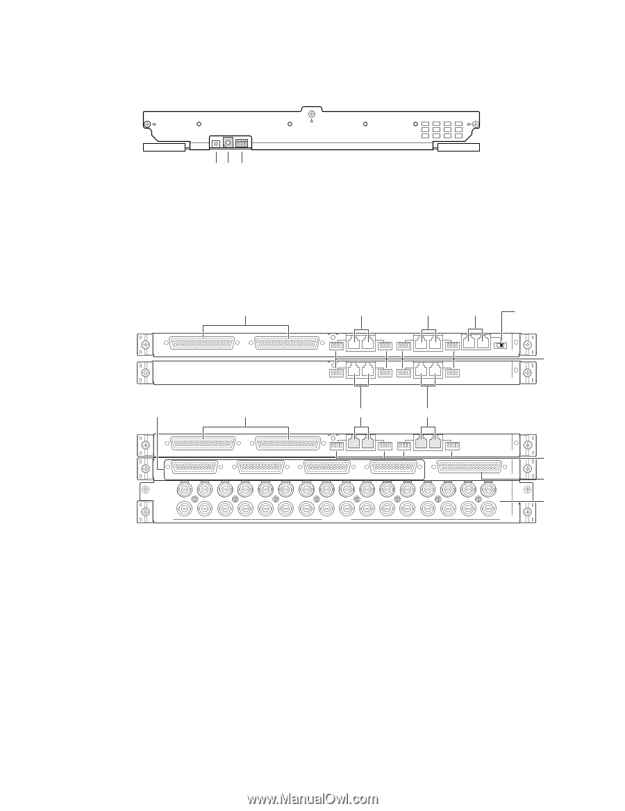
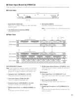
I Video Input Board WJ-PB65C32 Video input board is composed of a main board (installed into the front side) and rear boards (x 3)(installed into the rear side). G Front View RESET No. MODE eq w q Board Number Switch (No.) Refer to p. 17 Switch Settings for Video Input Main Board for details. w Input Mode Selection Switches (MODE) Set all switches to OFF. G Rear View y IN A-3 board IN B-3 board EXTENSION 3 OUT EXTENSION 2 OUT e Reset Switch (RESET) This button is pressed to reset this board. Note: In normal operation, you need not press the button. u u r t 4 3 MODE RS485 (CAMERA) MODE 4 3 2 1 OFF ON MODE RS485 (CAMERA) MODE OUT EXTENSION 1 IN TERM. IN A-3 2 1 MODE RS485 (CAMERA) MODE MODE RS485 (CAMERA) MODE IN B-3 i o y u u IN C-3 board IN X-2 board IN X-1 board EXTENSION 3 IN 4 3 2 1 EXTENSION 2 IN MODE RS485 (CAMERA) MODE MODE RS485 (CAMERA) MODE IN C-3 VIDEO OUT 4 VIDEO OUT 3 VIDEO OUT 2 VIDEO OUT 1 ALARM IN IN X-2 32 31 30 29 28 27 26 25 24 23 22 21 20 19 18 17 16 15 14 13 12 11 10 9 8 7 6 5 4 3 2 1 CAMERA IN IN X-1 i !0 !1 IN A-3/IN B-3/IN C-3 board Note: These boards are originally installed into WJ-SX650 and WJ-SX650U, and not supplied to optional video input boards. (IN A-3 board is installed into WJ-SX650U only.) r Extension Ports 1 (EXTENSION 1: IN, OUT) These ports connect to an optional card cage. t Termination Selector (TERM: ON, OFF) Turns on or off the line termination of r. y Extension Ports 2, 3 (EXTENSION 2, 3: IN, OUT) Each port connects to an optional card cage. u RS-485 Camera Ports 1 to 4 (RS485 (CAMERA) 1 to 4) These ports connect to RS-485 cameras. i RS-485 Camera Mode Switches 1 to 4 (MODE 1 to 4) These switches are moved to change the communication modes of u. IN X-2 board o Video Output Ports 1 to 4 (VIDEO OUT 1 to 4) These ports loop through video input signals supplied to !1. !0 Alarm Input Port (ALARM IN) Connects to an alarm sensor (door switch, etc.). IN X-1 board !1 Camera Input Connectors 1 to 32 (CAMERA IN 1 to 32) These connectors accept video input signals from cameras or recorders. 11
-
 1
1 -
2
-
3
-
4
-
5
-
 6
6 -
 7
7 -
 8
8 -
 9
9 -
 10
10 -
 11
11 -
 12
12 -
 13
13 -
 14
14 -
 15
15 -
 16
16 -
17
-
18
-
19
-
20
-
21
-
22
-
23
-
24
-
25
-
26
-
27
-
28
-
29
-
30
-
31
-
32
-
33
-
34
-
35
-
36
-
37
-
38
-
39
-
40
-
41
-
42
-
43
-
44
-
45
-
46
-
47
-
48
-
49
-
50
-
51
-
52
-
53
-
54
-
55
-
56
-
57
-
58
-
59
-
60
-
61
-
62
-
63
-
64
-
65
-
66
-
67
-
68
-
69
-
70
-
71
-
72
-
73
-
74
-
75
-
76
-
77
-
78
-
79
-
80
-
81
-
82
-
83
-
84
-
85
-
86
-
87
-
88
-
89
-
90
-
91
-
92
-
93
-
94
-
95
-
96
-
97
-
98
 |
 |